Sampling Theorem and Aliasing Explained
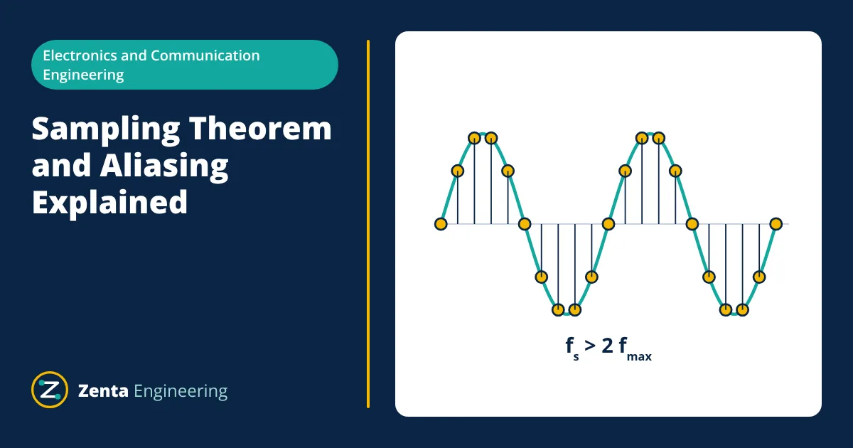
The sampling theorem states that a signal containing no frequencies above fmax can be reconstructed exactly from samples taken at a rate fs greater than 2 × fmax. If a signal contains frequencies above half the sampling rate, they are not lost: they reappear as false lower frequencies called aliases. An analog anti-aliasing filter before the ADC prevents this.
Why sampling needs a rule
Digital systems such as microcontrollers, data loggers, digital oscilloscopes and audio recorders measure analog signals at discrete instants. Between samples, nothing is recorded. The question is how often samples must be taken so that the original signal can be recovered without ambiguity. The Nyquist-Shannon sampling theorem answers it.
The Nyquist-Shannon sampling theorem
If a continuous signal is band-limited, meaning it contains no frequency components above fmax, it is completely described by samples taken at:
Two related terms are used:
- The Nyquist rate is 2 × fmax, the minimum sampling rate for a signal with highest frequency fmax.
- The Nyquist frequency is fs / 2, the highest frequency that a system sampling at fs can represent without ambiguity.
The theorem assumes ideal conditions: an exactly band-limited signal, perfectly timed samples and an ideal reconstruction filter. Real systems sample with a margin above 2 × fmax to make filtering practical.
What aliasing is
When a sine wave above the Nyquist frequency is sampled, the samples are identical to those of a sine wave at a lower frequency. The system cannot tell them apart, so the high frequency appears in the data as a false low frequency. This is aliasing.
A sampled frequency f appears at the alias frequency:
where k is the integer that brings the result into the range 0 to fs / 2.
- Given
- A data acquisition system sampling at fs = 1000 Hz. The input contains a 300 Hz signal of interest plus interference at 700 Hz and 1300 Hz.
- Find
- The frequencies at which the interference appears after sampling.
- Assumptions
- No anti-aliasing filter; ideal sampling.
- Solution
- Nyquist frequency = 1000 / 2 = 500 Hz
700 Hz: |700 − 1 × 1000| = 300 Hz
1300 Hz: |1300 − 1 × 1000| = 300 Hz - Answer
- Both interference signals alias to 300 Hz, exactly on top of the wanted signal, and cannot be separated after sampling
- Limitations
- Real signals contain many frequencies, and every component above 500 Hz folds back somewhere into the 0 to 500 Hz band.
The same effect is seen in films when a turning wheel appears to rotate slowly backwards. The camera samples the scene at a fixed frame rate, and the spokes move almost a full spoke spacing between frames.
Preventing aliasing
Anti-aliasing filter
The only reliable protection is an analog low-pass filter placed before the ADC. It attenuates all frequencies above the Nyquist frequency to a level below the ADC’s resolution, so nothing significant is left to alias.
A simple RC filter rolls off at only 20 dB per decade, which is rarely enough on its own. Practical anti-aliasing filters are often second order or higher, such as Sallen-Key or multiple feedback active filters, or a combination of an RC filter with a high sampling rate.
Choosing the sampling rate
Because real filters cannot cut off instantly, the sampling rate is chosen well above 2 × fmax, leaving a transition band for the filter:
| Application | Signal bandwidth | Typical sampling rate | Ratio |
|---|---|---|---|
| Telephone speech | About 3.4 kHz | 8 kHz | About 2.4 |
| CD audio | 20 kHz | 44.1 kHz | About 2.2 |
| Professional audio | 20 kHz | 48 kHz or 96 kHz | 2.4 or 4.8 |
| Industrial process signals | A few hertz | 10 Hz to 1 kHz | Often much more than 10 |
Oversampling
Sampling much faster than needed, then filtering and reducing the rate digitally (decimation), relaxes the analog filter. Sigma-delta ADCs use this technique: they sample at a very high rate, so a simple RC filter is enough, and a digital filter inside the converter removes the out-of-band content. Oversampling also spreads quantisation noise over a wider band, which improves resolution after filtering.
Quantisation: the other half of digitising
Sampling discretises time; quantisation discretises amplitude. An ideal N-bit ADC sampling a full-scale sine wave has a signal to quantisation noise ratio of:
A 12-bit ADC therefore has an ideal SNR of about 74 dB, and a 16-bit ADC about 98 dB. Real converters fall short of these figures because of their own noise and distortion.
Sampling jitter
The theorem assumes samples are taken at exactly equal intervals. Variation in the sampling instants, called jitter, adds noise that grows with signal frequency. For high-frequency, high-resolution converters, a low-jitter clock is as important as the ADC itself.
Reconstruction
To turn samples back into a continuous signal, a digital to analog converter (DAC) outputs a stepped waveform, and a reconstruction filter removes the high-frequency images around multiples of fs. In theory an ideal low-pass filter recovers the original signal exactly; in practice, oversampling and digital interpolation filters make the analog reconstruction filter simple.
A practical example: measuring a 50 Hz power signal
Consider a power monitor that must measure mains voltage and current up to the 25th harmonic on a 50 Hz system. The highest frequency of interest is 25 × 50 = 1250 Hz, so the Nyquist rate is 2500 Hz. Sampling at, for example, 6.4 kHz (128 samples per 50 Hz cycle) leaves a wide transition band. An anti-aliasing filter with a cut-off around 2 kHz then attenuates switching noise from drives and inverters, which can contain components of several kilohertz, before it can alias into the harmonic measurement range. Sampling synchronously with the mains, an integer number of samples per cycle, also makes the later Fourier analysis more accurate.
Practical checklist
- Find the highest frequency of interest and of any interference that could reach the ADC, including switching noise and mains harmonics.
- Choose fs with a comfortable margin above twice the bandwidth of interest.
- Design an anti-aliasing filter that attenuates everything above fs / 2 below the ADC’s noise floor.
- Consider oversampling with digital filtering where a sharp analog filter is hard to build.
- Never rely on software to remove aliasing after sampling.
Related reading
Frequently asked questions
Why is audio sampled at 44.1 kHz?
Human hearing extends to about 20 kHz. Sampling at 44.1 kHz puts the Nyquist frequency at 22.05 kHz, leaving a gap between 20 kHz and 22.05 kHz for the anti-aliasing filter to roll off.
Can aliasing be removed after sampling?
No. Once a high-frequency component has been sampled, its alias is indistinguishable from a real signal at the alias frequency. Aliasing must be prevented before the ADC with an analog anti-aliasing filter.
What is the Nyquist frequency?
It is half the sampling rate. It is the highest frequency that can be represented without aliasing at that sampling rate.
References
- A. V. Oppenheim and R. W. Schafer, Discrete-Time Signal Processing, Pearson
- S. W. Smith, The Scientist and Engineer's Guide to Digital Signal Processing, California Technical Publishing
- R. G. Lyons, Understanding Digital Signal Processing, Pearson
Get one engineering email a week
New articles, worked examples and study notes every week. Free, no spam, unsubscribe any time.

Electronics and Telecommunication engineer working in industrial instrumentation and automation. Writes the Electronics Engineering articles on Zenta Engineering. Editorial policy.
