Inverting and Non-Inverting Amplifier: Op-Amp Basics
The inverting and non-inverting amplifier are the two basic op-amp circuits. An operational amplifier (op-amp) is a very high gain differential amplifier. Used with negative feedback, its gain is set by two resistors:
- Inverting amplifier: gain = −Rf / Rin
- Non-inverting amplifier: gain = 1 + Rf / Rg
Real op-amps are limited by their gain bandwidth product, slew rate, output swing and input errors.
What an op-amp is
An op-amp has two inputs, the non-inverting input (+) and the inverting input (−), and one output. It amplifies the difference between the inputs:
The open-loop gain AOL is very large, typically 100,000 or more at DC. Without feedback, even a microvolt difference drives the output to one of its supply limits, which is why op-amps are almost always used with feedback from the output back to the inverting input.
The ideal op-amp and the golden rules
For analysis, an ideal op-amp is assumed to have infinite open-loop gain, infinite input impedance, zero output impedance and unlimited bandwidth. With negative feedback in place, two simple rules follow:
- No current flows into either input.
- The output adjusts so that the two inputs are at the same voltage (V+ = V−).
These rules, together with Ohm’s law and Kirchhoff’s current law, are enough to derive the gain of most op-amp circuits.
Inverting amplifier
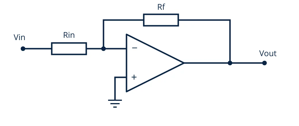
The input signal is applied through Rin to the inverting input, and Rf feeds the output back to the same input. The non-inverting input is grounded. By rule 2, the inverting input is held at 0 V, a virtual ground. The input current is Vin / Rin, and by rule 1 all of it flows through Rf, so Vout = −(Vin / Rin) × Rf:
The minus sign means the output is inverted, shifted by 180 degrees. The input impedance seen by the source is simply Rin, so Rin must not be too small for the source to drive.
Non-inverting amplifier
In the non-inverting amplifier, the signal goes to the non-inverting input. A divider made of Rf (output to inverting input) and Rg (inverting input to ground) feeds back a fraction of the output. Because the inputs are held equal, Vin = Vout × Rg / (Rf + Rg), which gives:
The gain is always 1 or more, and the output is in phase with the input. The input impedance is very high, because the signal drives an op-amp input directly. With Rf = 0 and Rg removed, the gain is exactly 1: this is the voltage follower or buffer, used to connect a high impedance source to a low impedance load.
Inverting and non-inverting amplifier compared
| Feature | Inverting | Non-inverting |
|---|---|---|
| Gain | −Rf / Rin | 1 + Rf / Rg |
| Phase | Inverted (180°) | In phase |
| Minimum gain magnitude | Any, including below 1 | 1 |
| Input impedance | About Rin | Very high |
| Common mode voltage at inputs | Near 0 V | Follows the input signal |
Other common op-amp circuits
The same golden rules explain many other circuits:
- Summing amplifier: several inputs, each through its own resistor, feed the virtual ground of an inverting amplifier. The output is the negative weighted sum of the inputs, which is used in audio mixers and in analog computation.
- Difference amplifier: amplifies the difference between two inputs with four matched resistors. It rejects voltage common to both inputs, which is useful for current sense resistors.
- Instrumentation amplifier: a difference amplifier with buffered high-impedance inputs, used with bridge sensors and thermocouples.
- Integrator: a capacitor in place of Rf makes the output proportional to the integral of the input, the basis of ramp generators and PI controllers.
- Comparator use: without feedback, the op-amp output switches between its limits depending on which input is higher. Dedicated comparator ICs are better for this because they recover faster from saturation.
Real op-amp limitations
Gain bandwidth product
The open-loop gain of a typical voltage-feedback op-amp falls with frequency. Its gain bandwidth product (GBW) is roughly constant, so the closed-loop bandwidth is approximately:
The noise gain is 1 + Rf / Rg for both configurations. For an inverting amplifier with a gain of −10, the noise gain is 11, the same as a non-inverting amplifier with a gain of 11.
Slew rate
The slew rate (SR) is the maximum rate of change of the output voltage, in V/µs. A sine wave of peak amplitude Vp and frequency f needs a slope of 2πfVp, so the largest undistorted frequency at that amplitude, the full power bandwidth, is:
- Given
- Op-amp with GBW = 1 MHz and slew rate 0.5 V/µs, used as a non-inverting amplifier with Rf = 100 kΩ and Rg = 10 kΩ. Output peak amplitude 5 V.
- Find
- Gain, small-signal bandwidth and full power bandwidth.
- Assumptions
- Single-pole op-amp response; supplies large enough for a 5 V peak output.
- Solution
- Gain = 1 + 100 / 10 = 11
Bandwidth ≈ 1,000,000 / 11 = 91 kHz
Full power bandwidth = 500,000 / (2π × 5) = 15.9 kHz - Answer
- Gain 11; small signals pass up to about 91 kHz, but a full 5 V peak output is limited to about 16 kHz by slew rate
- Limitations
- Datasheet GBW and slew rate are typical values that vary with supply voltage, load and temperature.
Other practical limits
- Output swing: the output cannot reach the supply rails unless the op-amp is a rail-to-rail output type, and swing falls further with heavy loads.
- Input offset voltage: a small built-in voltage between the inputs, amplified by the noise gain, which appears as a DC error at the output.
- Input bias current: small currents into the inputs, which create errors when they flow through large resistors.
- Common mode input range: the inputs must stay within the range the datasheet allows, which may not include the supply rails.
Choosing resistor values
Resistors in the range of about 1 kΩ to 100 kΩ suit most general purpose op-amps. Much smaller values load the output and waste power; much larger values increase noise and errors from bias current and stray capacitance. Use 1 percent tolerance resistors where the gain must be accurate, since the gain depends on their ratio.
Related reading
Frequently asked questions
What is a virtual ground?
In an inverting amplifier the non-inverting input is grounded. Negative feedback forces the inverting input to the same voltage, so it sits at 0 V even though it is not connected to ground. That node is called a virtual ground.
Why does an op-amp need negative feedback?
An op-amp's open-loop gain is enormous and varies between devices and with temperature. Negative feedback trades most of that gain for a precise, stable gain set by resistors, and it also widens bandwidth and reduces distortion.
What is the difference between gain bandwidth product and slew rate?
Gain bandwidth product limits how fast small signals can change for a given gain. Slew rate limits how fast the output voltage can change at all, which matters for large output swings. A circuit must satisfy both.
References
- A. S. Sedra and K. C. Smith, Microelectronic Circuits, Oxford University Press
- S. Franco, Design with Operational Amplifiers and Analog Integrated Circuits, McGraw-Hill
- R. Mancini (ed.), Op Amps for Everyone, Texas Instruments
Get one engineering email a week
New articles, worked examples and study notes every week. Free, no spam, unsubscribe any time.

Electronics and Telecommunication engineer working in industrial instrumentation and automation. Writes the Electronics Engineering articles on Zenta Engineering. Editorial policy.