Antenna Gain and Directivity: Radiation Pattern Explained
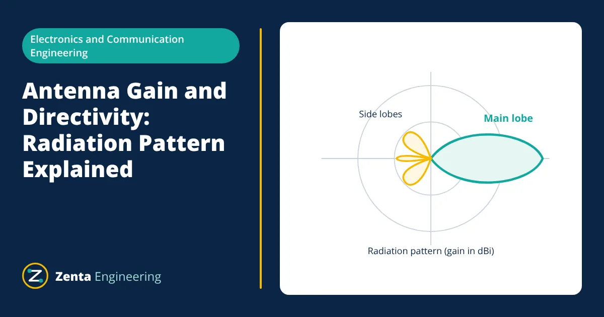
Antenna gain and directivity describe how well an antenna focuses energy in a chosen direction. An antenna converts electrical signals in a transmission line into radio waves, and back again on receive. Its radiation pattern shows how strongly it radiates in each direction. Directivity measures how concentrated that pattern is compared with an antenna radiating equally in all directions, and gain is directivity reduced by the antenna’s losses. Gain is usually quoted in dBi.
How an antenna radiates
Radio waves are produced by accelerating electric charges. When an alternating current flows in a conductor whose length is a significant fraction of a wavelength, the changing electric and magnetic fields detach from the conductor and travel outwards at the speed of light. The wavelength λ is set by the frequency f:
where c is about 3 × 10⁸ m/s in free space. At 100 MHz the wavelength is 3 m; at 2.4 GHz it is 12.5 cm.
Antennas are reciprocal: an antenna has the same pattern, gain and impedance whether it transmits or receives.
Radiation pattern
The radiation pattern is a plot of the radiated field or power against direction, usually shown as two cuts: the E-plane (containing the electric field) and the H-plane (containing the magnetic field). Key features:
- Main lobe: the direction of maximum radiation.
- Side lobes and back lobe: smaller lobes in other directions, usually unwanted.
- Half-power beamwidth (HPBW): the angle between the points where the power falls to half (−3 dB) of the maximum.
- Front-to-back ratio: main lobe level compared with the back lobe, in dB.
An isotropic antenna, which radiates equally in all directions, is a theoretical reference. An omnidirectional antenna, such as a vertical dipole, radiates equally in all horizontal directions but not upwards or downwards.
Antenna gain and directivity
Directivity D is the ratio of the radiation intensity in the direction of maximum radiation to the average radiation intensity over all directions. A larger D means a narrower, more focused beam.
Gain G includes the antenna’s efficiency η, which accounts for losses in conductors, dielectrics and mismatch:
Gain is usually expressed in decibels relative to an isotropic antenna:
A half-wave dipole has a directivity of about 1.64, or 2.15 dBi. Gain relative to a dipole, in dBd, is 2.15 dB lower than the dBi figure.
Impedance, matching and bandwidth
An antenna presents an impedance at its feed point. A half-wave dipole in free space has a radiation resistance of about 73 Ω at resonance. Maximum power transfers when the antenna impedance matches the transmission line, typically 50 Ω or 75 Ω. Mismatch reflects part of the power back, which is measured as:
- Return loss: how far the reflected power is below the incident power, in dB. Higher is better.
- VSWR: voltage standing wave ratio. A VSWR of 1:1 is a perfect match; 2:1 or better is a common acceptance level.
The bandwidth of an antenna is the frequency range over which its impedance match, gain and pattern stay within specified limits.
Polarisation
Polarisation is the orientation of the electric field of the radiated wave. It can be linear (vertical or horizontal) or circular (right- or left-hand). Transmit and receive antennas must have matching polarisation; a vertically polarised antenna receiving a horizontally polarised signal suffers a large loss in theory. Circular polarisation is common for satellite links because it is not affected by the orientation of the satellite.
Common antenna types
| Antenna | Typical gain | Pattern | Typical use |
|---|---|---|---|
| Half-wave dipole | 2.15 dBi | Omnidirectional around its axis | Reference antenna, FM and VHF |
| Quarter-wave monopole | Depends on ground plane | Omnidirectional | Vehicles, handheld radios |
| Yagi-Uda | Moderate to high, rising with element count | Directional | TV reception, point-to-point VHF and UHF |
| Microstrip patch | Moderate | Broad beam on one side | GPS, Wi-Fi, mobile devices |
| Horn | Moderate to high | Directional | Microwave test, feeds for dishes |
| Parabolic dish | Very high | Narrow beam | Satellite and microwave links |
Worked example: dipole length
- Given
- A half-wave dipole for 100 MHz.
- Find
- Free-space half wavelength and practical cut length.
- Assumptions
- Thin wire dipole; shortening factor of 0.95 for end effects.
- Solution
- λ = 300,000,000 / 100,000,000 = 3.0 m
λ / 2 = 1.5 m
Practical length ≈ 0.95 × 1.5 = 1.43 m, split into two arms of about 0.71 m - Answer
- Cut the dipole to about 1.43 m overall, then trim for best match using an antenna analyser
- Limitations
- The shortening factor depends on conductor diameter and nearby objects. Final tuning is done by measurement.
Antennas in a radio link
The Friis transmission equation relates received power to the antenna gains and the distance d between them in free space:
The term (4πd / λ)² is the free-space path loss. In decibels, path loss for d in metres and f in hertz is 20 log₁₀(d) + 20 log₁₀(f) − 147.55. At 2.4 GHz over 100 m this gives about 80 dB. Adding antenna gain at either end directly reduces the transmit power needed for the same received signal.
Effective aperture
A receiving antenna collects power from the wave passing it as if it had a capture area called the effective aperture Ae:
For the same gain, the effective aperture falls with the square of frequency. This is one reason why higher-frequency links need high-gain antennas to receive enough power, and why dish antennas grow more effective as frequency rises for a fixed physical size.
Choosing an antenna
- Start from the frequency band and required bandwidth.
- Decide the coverage: all directions (omnidirectional) or a point-to-point link (directional).
- Match the polarisation at both ends of the link.
- Check gain against the link budget, including path loss, cable loss and fade margin.
- Consider size, mounting, weather exposure and the effect of nearby metal, which can detune the antenna and distort its pattern.
Near field and far field
Close to an antenna, the fields are complex and the pattern is not yet formed. The far field, where the radiation pattern is valid, begins at roughly 2D² / λ for an antenna of largest dimension D. Antenna measurements must be made in the far field or corrected with near-field techniques.
Related reading
Frequently asked questions
Does a high-gain antenna amplify the signal?
No. An antenna is passive and cannot add power. Gain means it concentrates the radiated power in some directions at the expense of others, like a torch reflector focusing light.
What is the difference between dBi and dBd?
dBi is gain relative to an ideal isotropic antenna that radiates equally in all directions. dBd is gain relative to a half-wave dipole. Because a dipole has 2.15 dBi of gain, dBi = dBd + 2.15.
Why is a dipole cut slightly shorter than half a wavelength?
The conductor has a finite thickness and end effects that make it behave electrically longer than its physical length. Cutting it to about 95 percent of a free-space half wavelength brings it to resonance, where its impedance is close to purely resistive.
References
- C. A. Balanis, Antenna Theory: Analysis and Design, Wiley
- J. D. Kraus and R. J. Marhefka, Antennas for All Applications, McGraw-Hill
- IEEE Std 145, IEEE Standard for Definitions of Terms for Antennas
Get one engineering email a week
New articles, worked examples and study notes every week. Free, no spam, unsubscribe any time.

Electronics and Telecommunication engineer working in industrial instrumentation and automation. Writes the Electronics Engineering articles on Zenta Engineering. Editorial policy.
