What Is Mechatronics? Elements of a Mechatronic System
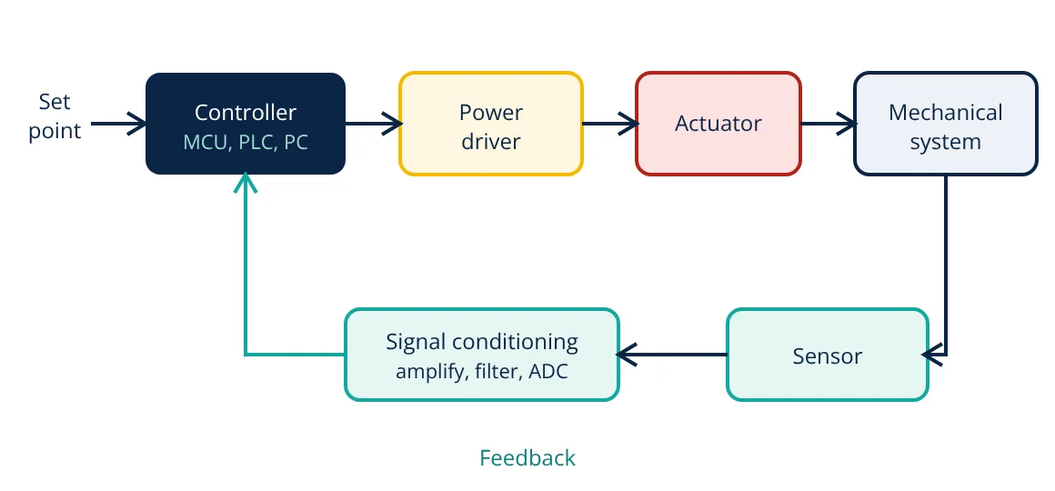
Mechatronics is the integrated design of mechanical systems with electronics, control and software. A mechatronic system has five main elements: the mechanical system being controlled, sensors that measure its state, signal conditioning and interfaces that convert signals, a controller (microcontroller, PLC or computer) that decides what to do, and actuators that act on the mechanism. Together they form a feedback loop that makes a machine accurate, adaptive and smart.
A modern car, a camera with autofocus, a 3D printer, an industrial robot and a hard disk drive all have something in common: precise mechanical motion controlled by electronics and software. Designing such products requires engineers to think across disciplines from the start, rather than adding controls to a finished mechanical design. That integrated approach is mechatronics.
Elements of a mechatronic system
1. Mechanical system
The physical part that moves or carries load: linkages, gears, belts, lead screws, bearings, frames and the load itself. Its mass, stiffness, friction and backlash decide how fast and precisely it can be controlled. Mechanical design draws on stress and strain, factor of safety and lubrication.
2. Sensors
Sensors measure what the controller needs to know:
- Position and speed: encoders, resolvers, potentiometers, LVDTs, hall effect sensors.
- Proximity and presence: inductive, capacitive, photoelectric and ultrasonic sensors.
- Force and pressure: strain gauges, load cells, pressure transmitters.
- Temperature: thermocouples, RTDs, thermistors.
- Acceleration and orientation: MEMS accelerometers and gyroscopes.
- Vision: cameras for inspection and guidance; see machine vision system components.
3. Signal conditioning and interfacing
Raw sensor signals are often small, noisy or in the wrong form. Conditioning circuits amplify, filter, isolate and convert them. Analog to digital converters turn voltages into numbers for the controller, and digital to analog converters and PWM outputs do the reverse. Op-amp circuits such as the inverting and non-inverting amplifier are standard building blocks, and the ADC must sample fast enough according to the sampling theorem.
4. Controller
The controller compares measurements with the desired value and computes commands. It may be a microcontroller in a consumer product, a PLC in a machine, a motion controller or an industrial PC. Algorithms range from simple on and off logic to PID control, state machines, model based and adaptive control. Software is as much a part of the product as the mechanics.
5. Actuators and drivers
Actuators convert energy into motion or force:
- Electric: DC motors, brushless motors, servo and stepper motors, solenoids, linear motors, piezo actuators.
- Hydraulic: cylinders and motors for very high force.
- Pneumatic: cylinders and grippers for fast, simple, low cost motion.
Power drivers (motor drives, H-bridges, solenoid drivers, valves) amplify low power controller signals to the energy level the actuator needs.
Open loop and closed loop control
In open loop control the controller sends commands without measuring the result, as in a simple stepper motor positioning system. In closed loop control, sensors feed back the actual output and the controller corrects the error continuously. For a PID controller, the output is:
where e(t) is the error between set point and measurement. Closed loop control compensates for disturbances and variations, which is why most precision mechatronic systems use it.
- Given
- A conveyor positioning axis uses a 1000 line incremental encoder read in quadrature (4 counts per line) on the motor shaft. The motor drives a belt pulley through a 10:1 gearbox, and the pulley moves the belt 100 mm per revolution.
- Find
- The position resolution at the belt.
- Assumptions
- No backlash or belt stretch; encoder counts read correctly at all speeds.
- Solution
- Counts per motor revolution = 1000 × 4 = 4000
Counts per pulley revolution = 4000 × 10 = 40,000
Resolution = 100 mm / 40,000 = 0.0025 mm - Answer
- About 2.5 µm per count, far finer than the accuracy the belt and gearbox can actually deliver
- Limitations
- Real accuracy is limited by mechanical backlash, belt elasticity and temperature, which is why mechanical and control design must be considered together.
The mechatronic design approach
Mechatronic design develops mechanics, electronics and software in parallel, with frequent integration and testing. Guidelines such as VDI 2206 describe a V model: define requirements, split them into domain specific designs, then integrate and verify step by step. Modelling and simulation, including model based design and digital twins, let teams test control strategies before hardware exists.
Benefits include fewer moving parts (software replaces cams and linkages), more functions and flexibility, better accuracy and self diagnosis.
Skills a mechatronics engineer needs
Mechatronics engineers combine several disciplines:
- Mechanical design: kinematics, dynamics, materials and machine elements.
- Electronics: analog and digital circuits, power electronics and motor drives.
- Control engineering: modelling, feedback, PID tuning and stability.
- Programming: embedded C, PLC languages and higher level tools for testing and data analysis.
- Measurement: sensor selection, calibration and signal processing.
- Systems thinking: managing interfaces and trade-offs between domains.
Because problems often sit at the boundaries, for example vibration caused by controller tuning or noise from a motor drive, the ability to work across disciplines is the defining skill.
Common challenges
Typical problems in mechatronic products include electrical noise from motor drives corrupting sensor signals, mechanical resonance that limits how aggressively a loop can be tuned, heat from electronics affecting mechanical tolerances, and software timing that is not deterministic. Good grounding and shielding, stiff mechanical design, careful thermal layout and real-time operating systems address these issues.
Testing each element alone and then the complete loop, with hardware in the loop simulation where possible, catches these problems early and cheaply.
Examples of mechatronic systems
- Automotive: anti-lock brakes, electronic stability control, engine management, electric power steering.
- Manufacturing: CNC machines, industrial robots, automated assembly and packaging machines.
- Consumer: washing machines, camera autofocus and image stabilisation, printers, drones.
- Medical: infusion pumps, surgical robots, prosthetic limbs.
- Aerospace: fly-by-wire flight controls and landing gear systems.
Frequently asked questions
Who coined the term mechatronics?
The term was introduced in Japan in 1969 by Tetsuro Mori, an engineer at Yaskawa Electric Corporation, to describe the combination of mechanical engineering and electronics in their products.
Is a washing machine a mechatronic system?
A modern one is. It uses sensors for water level, temperature, drum speed and load, a microcontroller that runs wash programs, and actuators such as the motor, pump, valves and door lock. The mechanical design and the control software are developed together.
What is the difference between mechatronics and robotics?
Robotics is one application of mechatronics. Mechatronics covers any product or machine that integrates mechanics, electronics, control and software, including cameras, cars, printers, medical devices and machine tools. Robots are mechatronic systems specialised for manipulation or mobility.
References
- W. Bolton, Mechatronics: Electronic Control Systems in Mechanical and Electrical Engineering, 7th ed., Pearson
- D. G. Alciatore and M. B. Histand, Introduction to Mechatronics and Measurement Systems, 5th ed., McGraw-Hill
- VDI 2206:2021 Development of mechatronic and cyber-physical systems, Verein Deutscher Ingenieure
- K. Ogata, Modern Control Engineering, 5th ed., Pearson
Get one engineering email a week
New articles, worked examples and study notes every week. Free, no spam, unsubscribe any time.