Machine Vision Components: Parts of a Vision System
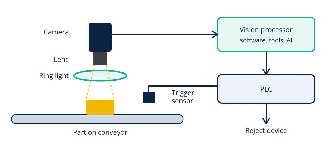
The main machine vision components are lighting, which creates contrast on the part; a lens, which forms the image; a camera with an image sensor, which converts light to pixels; a processor (smart camera, PC or embedded system) running vision software that finds, measures, reads or classifies features; and communication and I/O that send results to a PLC or robot and trigger rejects. The application defines each choice, starting from field of view and smallest feature to detect.
Machine vision gives automated equipment the ability to see. It checks that labels are present and straight, reads barcodes and printed dates, measures dimensions, finds defects on surfaces and tells robots where to pick parts. A reliable system depends on all components working together, so each one must be chosen for the task.
Machine vision components in detail
1. Lighting
Lighting is the most important and most underestimated component. Its job is to make the feature of interest stand out and hide everything else. Common techniques:
- Ring lights: general illumination around the lens; simple but can cause glare on shiny parts.
- Bright field (front) lighting: light reflects from flat surfaces into the camera.
- Dark field (low angle) lighting: only scratches, edges and embossed features scatter light into the lens, so they appear bright on a dark background.
- Backlighting: the part is between light and camera, giving a sharp silhouette for dimension and presence checks.
- Diffuse dome lighting: even, shadow free light for curved or shiny surfaces.
- Coaxial lighting: light along the lens axis for flat, reflective surfaces.
- Structured light: projected lines or patterns for 3D measurement.
Colour (wavelength) also matters: red light is common and cheap, coloured light can enhance or suppress coloured features, and infrared or ultraviolet reveal things invisible to the eye. Strobing the light synchronised with the camera freezes motion and overpowers ambient light.
2. Lens (optics)
The lens forms the image on the sensor. Key choices:
- Focal length: with the working distance, it sets the field of view.
- Aperture (f-number): controls brightness and depth of field; a smaller aperture gives more depth of field but needs more light.
- Resolution: the lens must resolve detail at least as fine as the sensor pixels.
- Telecentric lenses: keep magnification constant with distance and avoid perspective error, essential for precise gauging.
- Filters: polarisers to cut glare, band pass filters to block ambient light.
3. Camera and image sensor
The sensor, nowadays almost always CMOS, converts light into a grid of pixels. Choose:
- Resolution (number of pixels) to see the smallest feature.
- Frame rate and exposure time to match line speed.
- Shutter type: global shutter for moving parts; rolling shutter can distort fast motion.
- Monochrome or colour: monochrome gives better resolution and sensitivity; colour is used when colour must be judged.
- Area scan or line scan: line scan cameras build images line by line from moving webs or rotating parts.
- 3D cameras: laser triangulation, stereo, structured light or time of flight for height and volume.
Sensor performance can be compared with the EMVA 1288 standard.
4. Processor and software
Images are analysed by a smart camera with a built-in processor, a vision controller or an industrial PC with one or more cameras. Software provides tools such as:
- Image preprocessing (filters, thresholds, morphology).
- Pattern matching to locate parts regardless of position and rotation.
- Measurement of edges, distances, diameters and angles.
- Blob analysis for presence, count and area.
- Code reading (barcodes, 2D codes) and OCR for printed text.
- Colour analysis.
- Deep learning classification and defect detection for variable appearances that are hard to describe with rules.
5. Communication and I/O
Results are useful only when acted on. Vision systems use digital I/O for trigger inputs and pass or fail outputs, and industrial Ethernet protocols (such as PROFINET, EtherNet/IP or Modbus TCP, compared in Modbus RTU vs Modbus TCP) to exchange data with the PLC or robot. Camera interfaces include GigE Vision, USB3 Vision and CoaXPress, with the GenICam standard for common configuration.
Sizing the camera: field of view and resolution
A practical rule is that the smallest feature to be detected should span several pixels, often at least 2 to 4, and more for precise measurement. The required number of pixels along one axis is:
- Given
- A label on a box must be inspected across a 120 mm field of view (the longer side). The smallest defect to detect is 0.2 mm, and each defect should cover at least 3 pixels.
- Find
- The minimum sensor resolution along that axis.
- Assumptions
- Lens resolves the detail; field of view includes positioning tolerance.
- Solution
- Pixels = 120 / 0.2 × 3 = 1800 pixels
- Answer
- At least 1800 pixels across the 120 mm side, so a camera of about 2048 pixels wide (for example a 5 megapixel sensor) would be a sensible choice
- Limitations
- Check frame rate, exposure time for motion blur and lens resolution as well as pixel count.
Typical applications
Vision is used wherever human inspection would be too slow, too tiring or too inconsistent.
- Inspection: presence and absence, defects, fill level, cap and seal checks, print quality.
- Gauging: dimensions, hole positions, gaps and alignment.
- Identification: barcodes, 2D codes, OCR of dates and lot numbers for traceability.
- Guidance: locating parts for industrial robots, including random bin picking with 3D vision.
- Sorting by colour, size or quality in food, recycling and logistics.
Tips for reliable systems
- Start with sample parts, including good and every type of bad.
- Experiment with lighting first; it solves most problems.
- Fix the mechanics: consistent part position and distance.
- Shield from ambient light and vibration.
- Validate with large sample sets and track false rejects and escapes.
Machine vision is a key sensing element in mechatronic systems and in smart factories, where inspection data feeds analytics and digital twins. The image sensor itself works on the sampling theorem in space as well as time, which is why fine detail needs enough pixels.
Frequently asked questions
What is the difference between machine vision and computer vision?
Computer vision is the broad field of making computers understand images. Machine vision is its industrial application: cameras, lighting and software integrated into production equipment to inspect, measure, identify and guide, usually with strict requirements on speed, reliability and repeatability.
Why is lighting so important in machine vision?
The camera can only measure what the lighting makes visible. Good lighting maximises the contrast of the features of interest and suppresses everything else, which makes the software simpler and the result more reliable. Poor lighting is the most common cause of unreliable vision systems.
When should I use a smart camera instead of a PC based system?
A smart camera combines sensor, processor and software in one housing and suits single inspection points with moderate complexity. PC based systems with separate cameras suit multiple cameras, high resolution, heavy processing such as deep learning, or complex 3D applications.
References
- A. Hornberg (ed.), Handbook of Machine and Computer Vision, 2nd ed., Wiley-VCH
- E. R. Davies, Computer Vision: Principles, Algorithms, Applications, Learning, 5th ed., Academic Press
- EMVA 1288 Standard for Characterization of Image Sensors and Cameras, European Machine Vision Association
- GenICam and GigE Vision standards, Association for Advancing Automation and EMVA
Get one engineering email a week
New articles, worked examples and study notes every week. Free, no spam, unsubscribe any time.