PLC Hardware Selection: CPU, I/O Modules and Power Supply
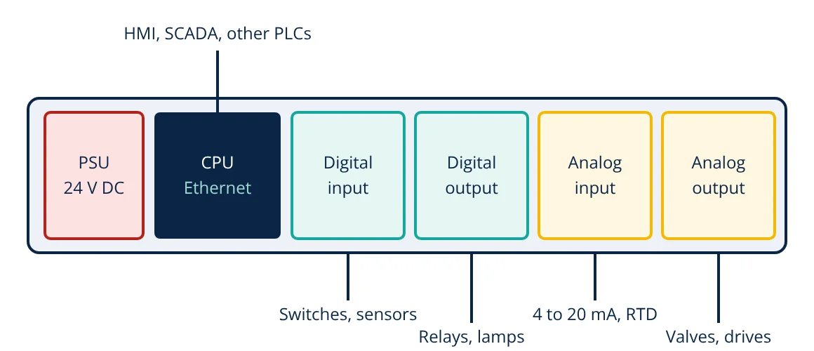
PLC hardware selection starts from the I/O list: count every digital and analog input and output, add 10 to 20 percent spare, then choose modules that match the signal types (24 V DC, 230 V AC, 4 to 20 mA, RTD, thermocouple). Next size the CPU for program memory, scan time, special functions and communication ports, then size the power supply from the total current of modules and field devices. Finally check environment, redundancy, certifications and spare parts support.
A programmable logic controller (PLC) is an industrial computer that reads sensors, runs a control program and drives actuators. Choosing the hardware is one of the first decisions in an automation project, and mistakes are expensive: an undersized CPU, the wrong input type or a missing communication port can force redesign of panels and wiring. A structured selection method avoids these problems.
Parts of a PLC system
- Power supply module (PSU): converts mains to the internal bus voltage and often supplies 24 V DC for field devices.
- CPU (processor module): runs the program, stores data and handles communication.
- I/O modules: digital inputs and outputs, analog inputs and outputs, and special modules such as high speed counters, motion and weighing.
- Rack, backplane or DIN rail bus: connects modules to the CPU.
- Communication modules: Ethernet based networks, PROFIBUS, Modbus serial, IO-Link masters and others.
- Remote I/O: I/O stations placed near the process, linked to the CPU by a network, cutting field cabling.
Step 1: Build the I/O list
List every field device with its tag, signal type and range. The basic signal categories are explained in AI, AO, DI and DO signals on InstrumentationBlog.in.
- Digital inputs (DI): push buttons, limit switches, proximity sensors, relay contacts, motor run feedback.
- Digital outputs (DO): contactor coils, solenoid valves, lamps, horns.
- Analog inputs (AI): 4 to 20 mA transmitters, 0 to 10 V signals, RTDs, thermocouples, load cells.
- Analog outputs (AO): control valve positioners, variable frequency drive speed references.
Group the totals by type and voltage, then add spare capacity, typically 10 to 20 percent, plus empty slots for growth.
Step 2: Choose I/O module types
Digital inputs: match the voltage (24 V DC is most common, 120 or 230 V AC in some plants), the sensor wiring (sinking or sourcing to suit PNP or NPN sensors) and the response time. High speed counters or encoder inputs are needed for fast pulses.
Digital outputs: choose the output type:
| Output type | Suits | Notes |
|---|---|---|
| Relay | AC or DC loads, mixed voltages | Isolated, but limited switching life and speed |
| Transistor | DC loads such as 24 V solenoids, fast pulses | Long life, fast, DC only |
| Triac | AC loads | No contact wear, small leakage current |
Check the current rating per point and per common group, and whether outputs are protected against short circuits.
Analog inputs: check signal type, resolution (12 to 16 bits typical), accuracy, number of channels, channel to channel isolation and whether the module powers 2-wire transmitters. Direct RTD and thermocouple modules avoid separate signal converters.
Analog outputs: check current or voltage output, resolution and load resistance limits.
Step 3: Size the CPU
- Program and data memory: estimate from the I/O count and the complexity of logic, PID loops, recipes and data logging, with generous spare.
- Scan time and speed: fast machines need short, deterministic scan times; process plants are usually less demanding.
- Functions: PID, motion control, safety, high speed counting, math and data handling.
- Communication: number and type of ports for HMI, SCADA, drives, remote I/O and other PLCs. Ethernet based protocols are now standard; Modbus remains widely used, as explained in Modbus RTU vs Modbus TCP.
- Programming: support for IEC 61131-3 languages and the software licence costs.
- Redundancy: hot standby CPUs and redundant networks for critical processes.
Step 4: Size the power supply
Add the backplane current of the CPU and every module, then add the 24 V DC current drawn by sensors, transmitters and output loads if they are fed from the same supply. Select a supply with margin, commonly 20 to 30 percent, and consider separate supplies for field devices so that a field short circuit does not stop the CPU. Redundant supplies with diode or decoupling modules are used where downtime is costly.
Step 5: Environment and certification
Check operating temperature, humidity, vibration and electrical noise against the module specifications and IEC 61131-2. Hazardous areas may need intrinsically safe barriers or certified remote I/O. Marine, railway and safety applications need specific approvals. Panel heat load, enclosure rating and cooling must also be checked.
- Given
- A pump station I/O list: 46 digital inputs (24 V DC, PNP sensors), 28 digital outputs (24 V DC solenoids and contactor coils), 10 analog inputs (4 to 20 mA, 2-wire transmitters) and 4 analog outputs (4 to 20 mA to drives). Modules available: 16 point DI, 16 point DO, 8 channel AI and 4 channel AO.
- Find
- Number of modules with 20 percent spare.
- Assumptions
- Spare applied to each signal type and rounded up; sinking DI modules to suit PNP sensors.
- Solution
- DI: 46 × 1.2 = 55.2, so 56 points; 56 / 16 = 3.5, so 4 modules (64 points)
DO: 28 × 1.2 = 33.6, so 34 points; 34 / 16 = 2.1, so 3 modules (48 points)
AI: 10 × 1.2 = 12 channels; 12 / 8 = 1.5, so 2 modules (16 channels)
AO: 4 × 1.2 = 4.8, so 5 channels; 5 / 4 = 1.25, so 2 modules (8 channels) - Answer
- 4 DI, 3 DO, 2 AI and 2 AO modules: 11 I/O modules plus CPU and power supply, with spare slots left on the rack
- Limitations
- Check the CPU’s maximum module count, backplane current and whether 2-wire transmitters can be powered from the AI modules.
Once installed, each analog input must be scaled from raw counts to engineering units in the program:
PLC hardware selection: final checks before ordering
- Confirm all field device types and voltages with the instrument and electrical lists.
- Check panel space, heat dissipation and cable entry for the chosen modules.
- Standardise on one product family across the plant to reduce spares and training.
- Check lifecycle status: avoid products near end of life.
- Order recommended spares: at least one of each module type and a spare CPU for critical systems.
The PLC is usually supervised by an HMI or a SCADA system, while large continuous processes may use a DCS instead. The electronics inside the CPU are related to a microcontroller.
Frequently asked questions
How much spare I/O should be allowed when selecting a PLC?
A common practice is to allow 10 to 20 percent spare installed I/O, plus spare slots or space for future modules. Project specifications often state the exact figure. Spare capacity avoids costly panel changes when small additions are made during commissioning or later.
What is the difference between sinking and sourcing inputs?
They describe the direction of current. A sourcing device supplies current to the load (PNP sensors are sourcing), while a sinking device provides the path to 0 V (NPN sensors are sinking). A sourcing sensor must be wired to a sinking input card and vice versa, so the sensor type decides which input module is suitable.
Should I choose a compact or a modular PLC?
Compact PLCs with built-in I/O suit small machines with a fixed, modest I/O count. Modular PLCs, with a separate CPU and plug-in modules on a rack or rail, suit larger systems, mixed signal types, remote I/O and plants that will grow. The cost per I/O point usually favours modular systems as size increases.
References
- IEC 61131-2:2017 Programmable controllers, Part 2: Equipment requirements and tests
- IEC 61131-3:2013 Programmable controllers, Part 3: Programming languages
- F. D. Petruzella, Programmable Logic Controllers, 5th ed., McGraw-Hill
- W. Bolton, Programmable Logic Controllers, 6th ed., Newnes
Get one engineering email a week
New articles, worked examples and study notes every week. Free, no spam, unsubscribe any time.