Automated Irrigation Control with Soil Moisture Feedback
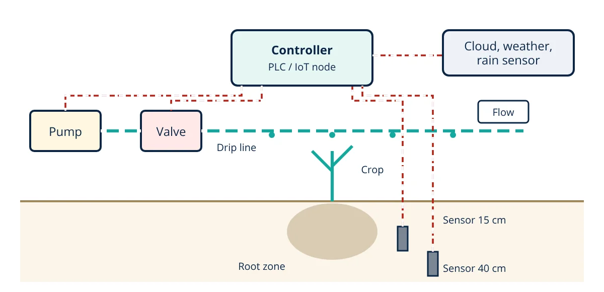
Automated irrigation control is a closed loop system that measures root zone soil moisture with sensors and switches irrigation automatically. A controller opens solenoid valves and starts the pump when moisture falls to a lower threshold set by management allowed depletion, then stops near field capacity, after a set volume, or at a maximum run time.
Irrigation is often scheduled by habit or a fixed timer. But crop water use changes daily with weather and growth stage, and rainfall or soil differences make fixed schedules wasteful. Closed loop control based on soil moisture applies water only when the crop needs it, saving water, energy and fertiliser, and preventing waterlogging and leaching.
Soil water basics
- Saturation: all pores full of water; drains quickly.
- Field capacity (FC): water held after free drainage stops, usually a day or two after heavy irrigation.
- Permanent wilting point (PWP): plants can no longer extract water.
- Total available water (TAW): the difference between FC and PWP in the root zone.
where θ is volumetric water content and Z_r the root depth. Irrigation is triggered when depletion reaches the management allowed depletion (MAD), a fraction p of TAW:
System architecture
Soil moisture sensors
| Sensor | Measures | Notes |
|---|---|---|
| Capacitance (FDR) | Volumetric water content via dielectric constant | Low cost, popular; needs soil specific calibration and good soil contact |
| TDR | Volumetric water content via pulse travel time | Accurate, less sensitive to salinity; higher cost |
| Tensiometer | Soil water tension (kPa) | Direct measure of how hard roots must pull; needs refilling; best in wetter range |
| Granular matrix / gypsum block | Tension via electrical resistance | Cheap, durable; slower response |
Sensors output analogue signals such as 4 to 20 mA or 0 to 10 V, or digital protocols such as SDI-12 and Modbus RS-485. Scaling these signals follows the same principles as other instrumentation signals.
Controller and logic
The controller compares measured moisture with setpoints and decides when to irrigate. Typical logic:
- Read sensors every few minutes; average multiple sensors and reject faulty readings.
- If moisture at the shallow sensor falls below the start threshold and no rain is forecast, open the zone valve and start the pump.
- Irrigate until the stop threshold is reached, a target volume has passed the flow meter, or a maximum run time expires.
- Use the deeper sensor to check that water is not draining below the roots; if it rises sharply, shorten future cycles.
- Lock out irrigation during rain, high wind (for sprinklers) or low tank level, and raise alarms for low pressure, no flow or high flow.
Simple systems use on-off control with hysteresis; advanced systems combine soil data with evapotranspiration forecasts and crop models. The control approach is the same as level control in industry, described in PLC hardware selection and SCADA system architecture.
Actuators and hydraulics
Solenoid valves (often 24 V AC latching types for battery operation) open zones; pump starters or VFDs run the pump; pressure switches and transmitters protect the system; fertigation injectors can be dosed in proportion to flow.
Communication and IoT
Wireless links (LoRaWAN, NB-IoT, cellular or Wi-Fi) connect sensors and valves across fields, and dashboards let farmers check moisture graphs and override schedules from a phone.
- Given
- A loam soil has θ_FC = 0.30 and θ_PWP = 0.14 (m³/m³). Tomato root depth is 0.5 m and p = 0.4. The drip system applies water with 90% efficiency. Daily crop water use is 6 mm.
- Find
- TAW, the start threshold moisture, the gross depth per irrigation and the approximate interval between irrigations.
- Assumptions
- Uniform root zone; no rain; irrigation refills to field capacity.
- Solution
- TAW = (0.30 − 0.14) × 500 mm = 80 mm
RAW = 0.4 × 80 = 32 mm
Start threshold θ = 0.30 − 32 ÷ 500 = 0.30 − 0.064 = 0.236
Gross depth = 32 ÷ 0.90 = 35.6 mm
Interval = 32 ÷ 6 ≈ 5.3 days - Answer
- Start irrigation when moisture falls to about 0.24 m³/m³, apply about 36 mm gross, roughly every 5 days in these conditions
- Limitations
- Drip often uses smaller, more frequent pulses to keep moisture steady; sensor calibration and spatial variability must be checked.
Key formulas for automated irrigation control
| Quantity | Formula | Symbols and units |
|---|---|---|
| Total available water | TAW = (θ_FC − θ_PWP) × Z_r | θ = volumetric water content in m³/m³, Z_r = root depth in mm, TAW in mm |
| Readily available water | RAW = p × TAW | p = management allowed depletion fraction (often 0.3 to 0.5), RAW in mm |
| Start threshold | θ_start = θ_FC − RAW ÷ Z_r | θ in m³/m³, RAW and Z_r in mm |
| Gross depth per irrigation | d_gross = RAW ÷ E_a | E_a = application efficiency as a fraction, d_gross in mm |
| Irrigation interval | Interval = RAW ÷ ET_c | ET_c = daily crop water use in mm/day, interval in days |
Weather based control
Soil sensors measure the result of crop water use; weather based controllers estimate it directly. They calculate reference evapotranspiration from temperature, humidity, wind and solar radiation, using the FAO Penman-Monteith method, multiply by the crop coefficient and subtract effective rain to keep a running soil water balance. Combining both approaches is most robust: the weather model predicts demand, and soil sensors correct the model and catch problems such as blocked emitters or unexpected drainage.
Installation and maintenance tips
A well installed sensor network is worth more than an expensive controller on its own, because control can only be as good as the measurements it receives.
- Calibrate sensors for the field soil or use manufacturer soil type settings, and check against gravimetric samples.
- Install sensors with good soil contact and no air gaps; protect cables from machinery and rodents.
- Use at least two sensor locations per irrigation zone and two depths per location.
- Check readings after each irrigation to confirm sensors respond.
- Record every change to thresholds so results can be compared between seasons.
- Keep spare batteries, valves and fuses, and test alarms at the start of each season.
Benefits of automated irrigation control
Field studies commonly report water savings of 20 to 50%, energy savings from shorter pumping times, better yields and quality from steadier moisture, less nutrient leaching and reduced labour. Automated irrigation control is a building block of precision agriculture and works with both systems compared in drip vs sprinkler irrigation.
Automated irrigation control interview and viva questions
- What is field capacity? It is the water held in the soil after free drainage stops, usually a day or two after heavy irrigation, and it sets the upper threshold at which irrigation stops.
- What does management allowed depletion control? MAD is the fraction p of total available water the crop may use before irrigating, so it sets the start threshold; it is often 30 to 50%.
- Why are sensors installed at two depths? The shallow sensor triggers irrigation, while the deeper sensor shows whether water is draining below the roots so that future cycles can be shortened.
- Why is hysteresis used in on-off irrigation control? Separate start and stop thresholds prevent the valves and pump from switching rapidly around a single setpoint.
- Why combine soil sensors with weather based control? The weather model predicts crop demand from evapotranspiration, while soil sensors correct the model and catch problems such as blocked emitters or unexpected drainage.
Frequently asked questions
Where should soil moisture sensors be installed?
In the active root zone of a representative part of the field, typically at two or more depths, for example one in the upper root zone and one near the bottom of the roots. For drip systems, place sensors within the wetted bulb near an emitter. Avoid unusual spots such as low wet areas, compacted tracks or field edges unless they are the area being managed.
What is management allowed depletion?
Management allowed depletion (MAD) is the fraction of the plant available water that the grower allows to be used before irrigating. It is often 30 to 50% depending on crop sensitivity and growth stage. When soil moisture falls to the MAD threshold, irrigation starts, refilling the root zone towards field capacity.
Can I use a simple timer instead of sensors?
Timers are cheap but water on a fixed schedule regardless of weather, rain or crop stage, which often leads to over or under irrigation. Sensor based or weather based controllers adapt to actual conditions, typically saving 20 to 50% of water in studies, while maintaining or improving yields.
References
- FAO Irrigation and Drainage Paper 56, Crop Evapotranspiration: Guidelines for Computing Crop Water Requirements, 1998
- S. Irmak et al., Irrigation Water Management Using Soil Moisture Sensors, ASABE and University of Nebraska Extension
- ASABE S526.4, Soil and Water Terminology
- R. G. Evans and E. J. Sadler, Methods and technologies to improve efficiency of water use, Water Resources Research, 2008
- IEC 61131-3, Programmable controllers: Programming languages
Get one engineering email a week
New articles, worked examples and study notes every week. Free, no spam, unsubscribe any time.