PLC Ladder Logic Basics with Examples
PLC ladder logic is a graphical programming language that looks like a relay wiring diagram. Two vertical rails carry imaginary power, and each horizontal rung holds input conditions (contacts) on the left and an output instruction (coil, timer or counter) on the right. Contacts in series form AND logic, contacts in parallel form OR logic, and the PLC evaluates every rung from top to bottom on each scan.
PLC ladder logic grew out of the relay panels it replaced. Plant electricians already read relay drawings, so early PLC makers gave them a programming language with the same look. Today Ladder Diagram (LD) is one of the programming languages standardised in IEC 61131-3, and it is still the most common choice for discrete control of motors, conveyors, valves and machines. This article explains the symbols, how the PLC executes them, the standard building blocks and a worked timing example.
Ladder logic symbols: rails, rungs, contacts and coils
A ladder program is drawn between a left power rail and a right power rail. Each rung is one logical statement. When a continuous path of true conditions exists from the left rail to the output, the rung is true and the output is energised.
| Symbol | Name | Meaning in the program |
|---|---|---|
| Two vertical bars | Normally open contact | True when the referenced bit is 1 |
| Two bars with a slash | Normally closed contact | True when the referenced bit is 0 |
| Circle or brackets | Output coil | Writes 1 to the bit while the rung is true |
| Coil with S or L | Set (latch) coil | Writes 1 and holds it until reset |
| Coil with R or U | Reset (unlatch) coil | Writes 0 to a latched bit |
| Box | Function block | Timer, counter, compare, math, move and so on |
An important point for beginners: a contact in the program does not describe the physical switch. It describes a test on a bit in memory. A normally open contact asks “is this bit on?” and a normally closed contact asks “is this bit off?”. The same input bit can be used in any number of contacts, in any rung.
Addresses depend on the manufacturer. Some families use tag names, others use addresses such as I0.0 for an input and Q0.0 for an output. Good practice is to give every bit a descriptive tag, such as Start_PB or Conveyor_Run.
How the PLC executes ladder logic: the scan cycle
A PLC does not evaluate all rungs at the same instant the way a relay panel works. It runs a repeating scan cycle:
- Read inputs: the state of every input module is copied into an input image table.
- Execute the program: rungs are solved from top to bottom and left to right, using the image table values, and results are written to an output image table.
- Update outputs: the output image table is written to the output modules.
- Housekeeping: communication and self diagnostics, then the cycle repeats.
Typical scan times range from about one millisecond to tens of milliseconds, depending on program size and CPU speed. Because rungs are solved in order, a bit written in rung 10 is already updated when rung 11 reads it, but rung 5 will only see it on the next scan. This order matters for edge detection, interlocks and duplicate coils, and it is the reason the same coil should be written in only one rung.
Basic logic: AND, OR and NOT
The three basic logic gates map directly onto rung patterns:
- AND: contacts in series. A press runs only if Guard_Closed AND Two_Hand_OK are both true.
- OR: contacts in parallel branches. A light turns on if Switch_A OR Switch_B is on.
- NOT: a normally closed contact. A heater runs while High_Temp is NOT set.
More complex Boolean expressions are built by combining series and parallel branches. Long chains are easier to maintain when split into intermediate internal bits with clear names.
The start and stop seal-in circuit
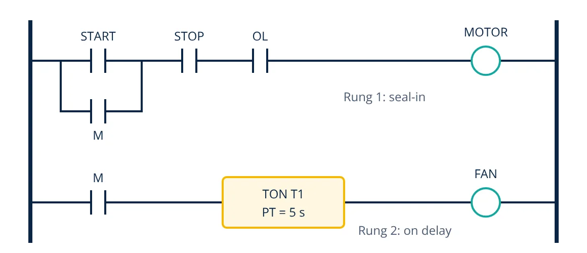
The most important ladder pattern is the three-wire motor control circuit, also called a seal-in or holding circuit. A momentary start push button energises the motor coil, and a contact of the motor bit in parallel with the start button keeps the rung true after the button is released.
How rung 1 works:
- At rest, STOP and OL inputs are on (healthy normally closed devices), but START and M are off, so the motor is off.
- Pressing START closes the path through STOP and OL, so the MOTOR coil turns on and the M bit becomes 1.
- On the next scan the M contact in the parallel branch is true, so the rung stays true after START is released.
- Pressing STOP, or an overload trip, breaks the series path. M turns off, the seal-in contact opens and the motor stays off until START is pressed again.
The stop button and overload contact are wired as normally closed devices and programmed as contacts that test for the on state. If a stop wire breaks, the input drops out exactly as if STOP were pressed, so a wiring fault fails safe. Emergency stop functions, however, must not rely on the PLC program alone: IEC 60204-1 requires stop categories and safety related control that are implemented with suitably rated hardware or safety PLCs.
Timers and counters in PLC ladder logic
IEC 61131-3 defines standard timer and counter function blocks used in most modern PLCs:
- TON (on delay): the output Q turns on when the input has been true continuously for the preset time PT. If the input drops early, the elapsed time ET resets.
- TOF (off delay): Q turns on with the input and stays on for PT after the input turns off. Used for fan run on after a heater stops.
- TP (pulse): gives a fixed length pulse of duration PT when triggered.
- CTU (count up): counts rising edges on CU; Q turns on when the count reaches the preset PV. A reset input R clears the count.
- CTD (count down) and CTUD: count down, or up and down, for stock levels and batch counting.
Rung 2 in the figure uses a TON block: the fan starts only after the motor bit has been on for 5 seconds. Counters are typically used for boxes on a conveyor, parts per batch or cycles before a maintenance alarm. Beyond these, ladder editors provide compare, math, move and PID instructions, so analog values can be handled too, for example after scaling a 4 to 20 mA input.
- Given
- A conveyor jam sensor is wired to a 24 V DC input with a 3 ms input filter delay. The PLC scan time is 10 ms. The stop output is a transistor output with a 1 ms switching delay.
- Find
- The worst case time between the sensor changing state and the output switching.
- Assumptions
- The input changes just after the input read of a scan, so it is only seen at the next scan; the program then needs that full scan before the output update. Communication delays are ignored.
- Solution
- Worst case delay = input delay + 2 × scan time + output delay
= 3 ms + 2 × 10 ms + 1 ms
= 24 ms - Answer
- About 24 ms worst case response time
- Limitations
- Real scan times vary from scan to scan; use the maximum scan time reported by the CPU. Relay outputs switch more slowly than transistor outputs, and safety functions need a validated response time from the safety system documentation.
Good practice for readable ladder programs
- Write each output coil in one rung only. Use internal bits to combine conditions.
- Keep a standard order: inputs and conditioning first, then sequence logic, then outputs and alarms.
- Comment every rung with what it does and why, not just the tag names.
- Use interlocks for opposing outputs, such as forward and reverse contactors, both in the program and in hardware.
- Test with forced inputs or a simulator before connecting real actuators.
Ladder programs run on the CPU and I/O chosen during PLC hardware selection, and the internal CPU is a dedicated microcontroller or microprocessor running the scan. Operators usually monitor the logic through an HMI or a SCADA system. More PLC programming topics are collected in the PLC category on InstrumentationBlog.in.
Frequently asked questions
Why is a stop button wired normally closed but programmed with a normally open contact?
A normally closed stop button keeps the input energised while the circuit is healthy. If the wire breaks, the input turns off just as if the button were pressed, so the machine stops. In the program the input is examined for the on state (a normally open contact), which is true while the healthy button is not pressed.
What is the difference between a coil and a set (latch) coil?
A normal output coil follows the logic of its rung on every scan: it is on only while the rung is true. A set or latch coil turns the bit on and leaves it on even after the rung becomes false, until a reset or unlatch instruction clears it. Seal-in rungs are often preferred because their behaviour after a power loss is easier to see.
Is ladder logic still used in modern PLCs?
Yes. Ladder Diagram is one of the languages defined in IEC 61131-3, alongside Function Block Diagram, Structured Text and Sequential Function Charts, and it remains widely used for discrete machine control because electricians can read it like a relay drawing.
References
- IEC 61131-3:2013 Programmable controllers, Part 3: Programming languages
- F. D. Petruzella, Programmable Logic Controllers, 5th ed., McGraw-Hill
- W. Bolton, Programmable Logic Controllers, 6th ed., Newnes
- J. R. Hackworth and F. D. Hackworth, Programmable Logic Controllers: Programming Methods and Applications, Prentice Hall
- IEC 60204-1:2016 Safety of machinery, Electrical equipment of machines, Part 1: General requirements
Get one engineering email a week
New articles, worked examples and study notes every week. Free, no spam, unsubscribe any time.