SCADA System Architecture Explained
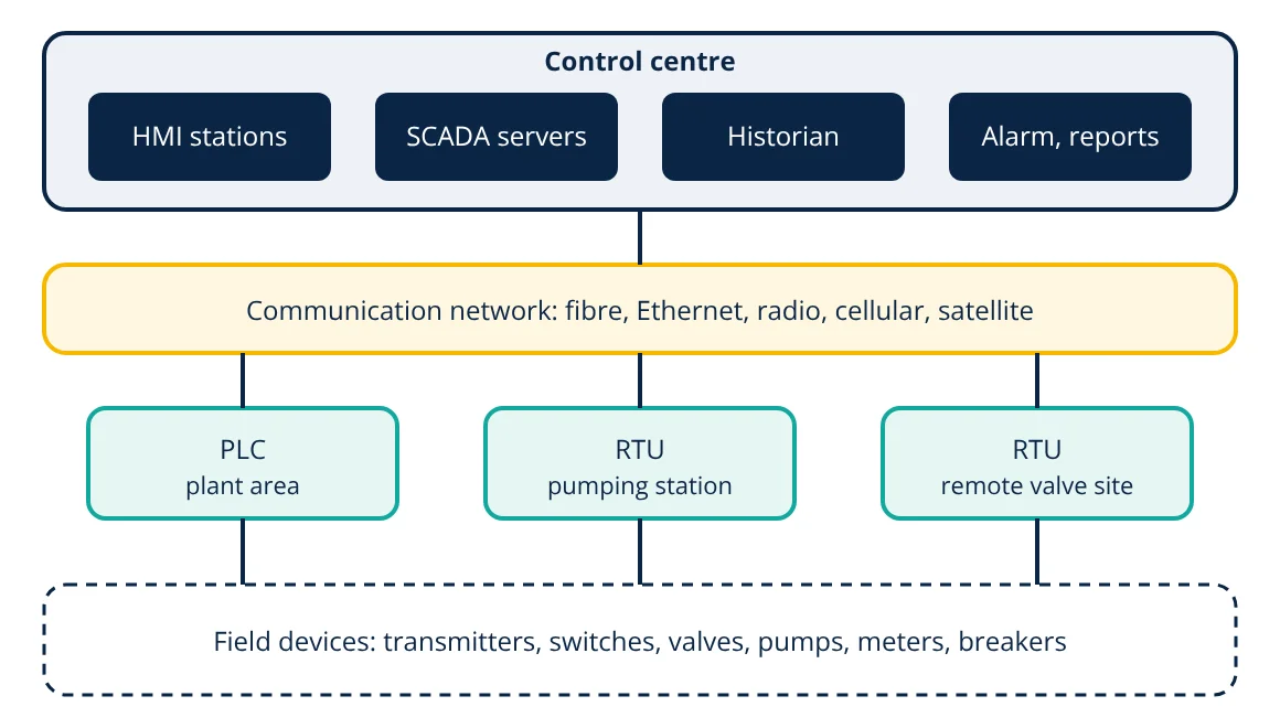
A SCADA system architecture has four layers: field devices (sensors and actuators), local controllers (PLCs and RTUs) that read them and run control logic, a communication network that links remote sites to the control centre, and SCADA servers with operator HMI screens, an alarm system and a historian that stores data. SCADA supervises and coordinates large or widely spread systems such as pipelines, water networks and power grids.
SCADA stands for Supervisory Control and Data Acquisition. It lets a small team of operators monitor and control equipment spread over a factory, a city or hundreds of kilometres of pipeline from one control room. Understanding its architecture helps engineers specify systems, troubleshoot communication problems and secure them against cyber attack.
Layers of a SCADA system architecture
1. Field devices
Sensors and transmitters measure flow, pressure, level, temperature, voltage and current; actuators such as valves, pumps, motors and circuit breakers act on the process. Signals are discrete (on or off) or analog (usually 4 to 20 mA), or digital over fieldbuses.
2. Local controllers: PLCs and RTUs
Programmable logic controllers read field signals and run fast control logic locally; choosing their hardware is covered in PLC hardware selection. Remote terminal units are built for remote sites: rugged, low power, often solar or battery backed, and able to store time stamped data during communication outages and send it later. Intelligent electronic devices (IEDs), such as protection relays in substations, also report to SCADA.
Local controllers keep the process safe on their own. If the link to the centre fails, pumps still stop on low level and valves still close on high pressure.
3. Communication network
SCADA networks must cover the distances involved: plant Ethernet and fibre inside a site, and licensed radio, cellular, microwave, leased lines or satellite to remote sites. Common protocols include Modbus (serial RTU and TCP), DNP3 in water and electric utilities, IEC 60870-5-101/104 and IEC 61850 in power systems, and OPC UA for integration between systems. Polling, report by exception and time stamping are used to make the best use of limited bandwidth. The two Modbus variants are compared in Modbus RTU vs Modbus TCP.
4. Control centre: servers, HMI and historian
- SCADA servers poll or receive data from all controllers, maintain the real-time database of tags, execute supervisory logic and send operator commands.
- HMI clients display process graphics, trends and alarms, and let operators change set points or start and stop equipment.
- Alarm management detects abnormal conditions, prioritises them and records operator acknowledgements. ISA-18.2 gives a life cycle for designing alarm systems that do not flood operators.
- Historian stores time series data efficiently for trends, reports, compliance and analysis.
- Engineering workstation for configuring tags, graphics and logic.
- Interfaces to business systems such as maintenance management, billing and energy management.
Generations of SCADA architecture
- Monolithic: mainframe or minicomputers with proprietary protocols, isolated from other systems.
- Distributed: several networked computers on a LAN sharing tasks, still mostly proprietary.
- Networked: open standards, Ethernet and IP, wide area networks and standard databases.
- Internet of Things and cloud: web based HMIs, cloud historians and analytics, MQTT and OPC UA connections, often linked to digital twin applications.
Redundancy and availability
Critical SCADA systems duplicate the components whose failure would blind operators: hot standby SCADA servers, redundant network paths, dual communication links to key sites, redundant historians and uninterruptible power supplies. Failover is tested regularly. Each remote controller holds a local copy of its logic so it keeps running safely if the centre is unavailable.
Security
Modern SCADA systems are networked, so they are exposed to cyber threats. Good practice from IEC 62443 and NIST SP 800-82 includes:
- Segmentation: separate the control network from the business network with firewalls and a demilitarised zone (DMZ); use zones and conduits.
- Access control: unique accounts, least privilege and multi-factor authentication for remote access.
- Secure protocols: use encrypted and authenticated versions where available, such as OPC UA security and DNP3 Secure Authentication.
- Patch and asset management: know every device and keep software supported.
- Monitoring and backup: detect unusual traffic and keep tested backups of configurations and programs.
Data flow in practice
A pumping station RTU measures tank level and pump status every second. The SCADA server polls it every few seconds, or the RTU reports by exception when a value changes by more than a set deadband. The server updates its real-time database, checks alarm limits, writes the value to the historian and refreshes the operator’s screen. When the operator changes a level set point, the command travels back to the RTU, which confirms it, and the change is logged with user name and time for audit. Time stamps from the RTU, synchronised by GPS or network time, keep the sequence of events correct even when data arrives late.
Historical data from the same flow later supports reports on energy use, compliance and asset performance.
Communication health is itself monitored, so operators are alerted at once if a site stops reporting, and stale values are flagged on screen.
SCADA vs DCS
SCADA and a distributed control system (DCS) overlap but have different origins. SCADA is event and data acquisition oriented, often across wide areas with slow or unreliable links, using PLCs and RTUs from different vendors. A DCS is process oriented, typically inside one plant, with tightly integrated controllers, engineering tools and operator stations from one vendor, running many continuous control loops. Large facilities often combine both.
Typical applications
- Water and wastewater networks: reservoirs, pumping stations, treatment plants.
- Oil and gas pipelines: compressor and pump stations, block valves, leak detection.
- Electric power: substations, transmission and distribution networks, renewable plants such as wind and solar farms.
- Building and campus utilities, railways and tunnels, irrigation systems.
To learn the software side hands on, see the free SCADA training resources list on InstrumentationBlog.in.
Frequently asked questions
What is the difference between SCADA and HMI?
An HMI is the operator interface: screens that show values and let operators issue commands, often for one machine or panel. SCADA is the wider system that gathers data from many controllers and sites, stores history, manages alarms and provides HMIs as one of its parts.
What is the difference between an RTU and a PLC?
Both read field signals and run logic. RTUs are designed for remote, often unmanned sites: low power, wide temperature range, time stamped data logging and communication over radio, cellular or serial links. PLCs are optimised for fast local control. Modern products overlap, and many SCADA systems use PLCs as RTUs.
Is SCADA used for control or only monitoring?
Both, but at a supervisory level. Fast control loops run in PLCs or RTUs at the sites. SCADA sends set points and start or stop commands and supervises the overall system, so it can keep running safely even if the communication link to the centre is lost.
References
- IEC 62443 Industrial communication networks, Security for industrial automation and control systems (series)
- NIST SP 800-82 Rev. 3, Guide to Operational Technology (OT) Security, 2023
- ANSI/ISA-18.2-2016 Management of Alarm Systems for the Process Industries
- S. A. Boyer, SCADA: Supervisory Control and Data Acquisition, 4th ed., ISA
Get one engineering email a week
New articles, worked examples and study notes every week. Free, no spam, unsubscribe any time.