What Is a DCS? Architecture and Applications
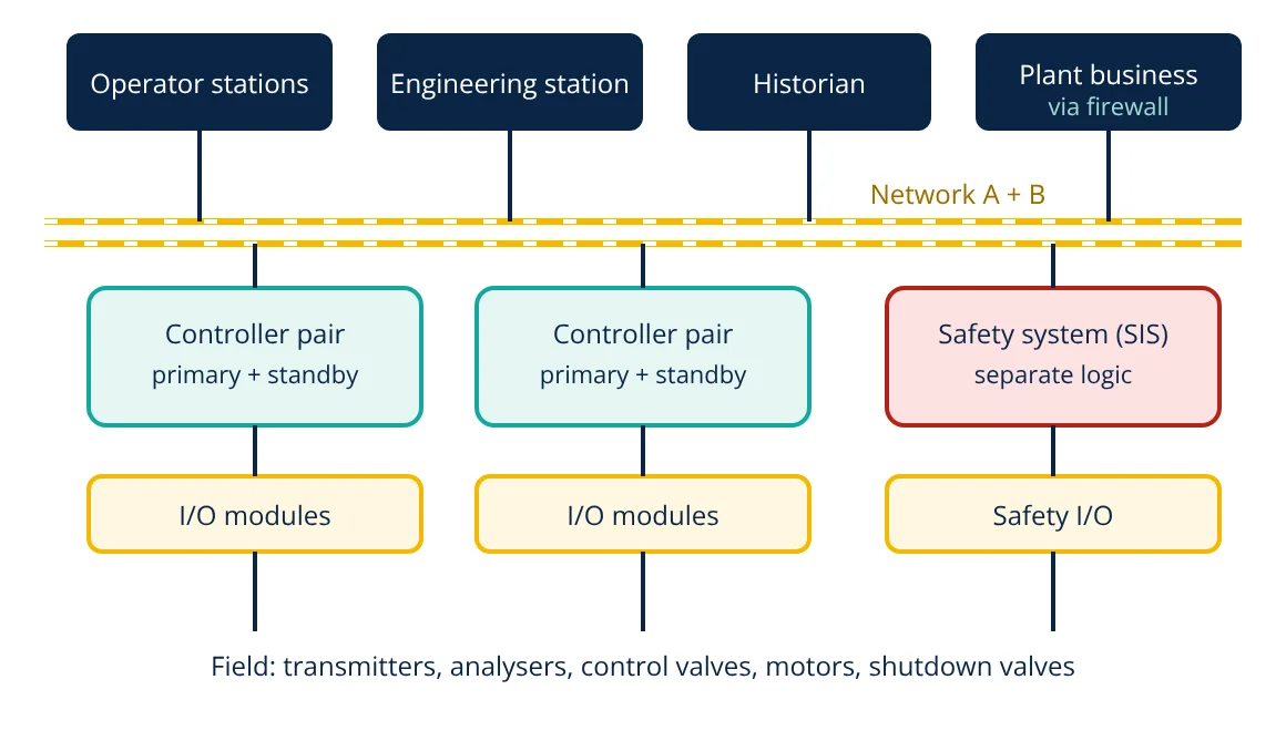
A distributed control system (DCS) controls a large continuous process using many controllers spread around the plant, all tied to a common control network, operator stations, engineering station and historian. The DCS architecture places control close to the process for reliability, while operators supervise everything from one integrated system. DCSs are standard in refineries, chemical plants, power stations, pharmaceuticals and pulp and paper mills.
Before DCSs, process plants were run from large panels of individual analog controllers and recorders, or from one central computer whose failure stopped the whole plant. The first commercial DCSs appeared in the mid 1970s and solved both problems: control was distributed across many microprocessor based controllers, so a single failure affected only a small part of the plant, while operators gained a unified view through video displays.
DCS architecture layers
Field level
Transmitters, analysers, switches, control valves and motor starters connect to I/O by 4 to 20 mA (often with HART digital data), discrete signals or fieldbuses such as FOUNDATION Fieldbus and PROFIBUS PA. Sensor principles and valve selection are covered in process instrumentation articles on InstrumentationBlog.in.
I/O subsystem
I/O modules convert field signals for the controller. Modern DCSs offer configurable or universal I/O, where each channel can be set in software as AI, AO, DI or DO, which simplifies design and late changes. I/O can be in marshalling cabinets in the control building or in remote cabinets near the process.
Controllers
Each controller handles a process area or unit, executing control strategies built from function blocks: PID, analog input with alarms, ratio, cascade, split range, selectors, sequences and interlocks. Controllers run on a fixed, deterministic cycle, often a fraction of a second, and are usually supplied as redundant pairs: the standby tracks the primary and takes over without disturbing the process if the primary fails.
Control network
A redundant, deterministic network links controllers and workstations. It is usually industrial Ethernet with two independent paths, so a cable or switch failure does not interrupt communication.
Operator and engineering stations
Operator stations show process graphics, faceplates, trends and alarms. Good graphics follow ISA-101 principles: grey backgrounds, colour reserved for abnormal conditions, and overview displays that show the state of the whole plant. Engineering stations configure the database, control strategies and graphics, and download changes to controllers, often online without stopping the plant.
Historian and higher systems
The historian records process data and events. Through firewalls, data flows to plant information systems, maintenance, laboratory and enterprise systems, and to advanced process control and optimisation applications.
How a DCS control loop works
A typical loop such as level control reads the level transmitter through an AI block, compares it with the set point in a PID block and sends an output through an AO block to the outlet valve. Operators can switch the loop between manual, automatic and cascade modes, change the set point and see the output, all from a standard faceplate.
- Given
- A distillation unit has 180 analog inputs, 70 analog outputs, 250 digital inputs and 120 digital outputs. One controller pair is rated for up to 500 I/O points with the planned loop count and scan rate.
- Find
- The number of controller pairs, allowing 20 percent spare.
- Assumptions
- The vendor’s rating already covers the control strategies planned; I/O split by process area.
- Solution
- Total I/O = 180 + 70 + 250 + 120 = 620 points
With 20 percent spare: 620 × 1.2 = 744 points
744 / 500 = 1.49, so 2 controller pairs - Answer
- Two redundant controller pairs, for example one for the column and reboiler area and one for feed and product handling
- Limitations
- Real sizing also checks controller CPU and memory load from the actual function blocks, communication load and the client’s spare philosophy.
DCS vs PLC vs SCADA
| Feature | DCS | PLC system | SCADA |
|---|---|---|---|
| Main use | Continuous process control in one plant | Machine and discrete control, smaller processes | Supervision of widely spread assets |
| Control loops | Hundreds to thousands of PID loops | Fewer loops, fast logic | Supervisory; control in field PLCs or RTUs |
| Engineering | Single integrated database and tools | Separate tools for PLC, HMI and network | Configured on top of varied controllers |
| Redundancy | Standard and built in | Optional | Server and link redundancy |
| Typical scale | Large plants | Machines, skids, packages | Pipelines, water, power networks |
The boundaries have blurred: large PLC based systems behave much like a DCS, and DCSs integrate PLCs for packaged equipment. See SCADA system architecture and PLC hardware selection for comparison.
Alarm management and operator effectiveness
A large plant can have thousands of configured alarms. Poorly designed alarm systems flood operators during upsets, hiding the important messages. Good DCS projects follow ISA-18.2 and IEC 62682: each alarm must have a defined cause, consequence, operator response and priority; nuisance and chattering alarms are removed; and alarm rates are monitored against targets. Well designed graphics to ISA-101 and clear alarm presentation help operators recognise abnormal situations early.
Engineering and life cycle
A DCS project moves through design (I/O lists, control narratives, loop diagrams), configuration, factory acceptance testing with simulated I/O, site installation, loop checks, commissioning and start-up. During decades of operation the system is maintained, patched, expanded and eventually migrated to newer hardware, often while the plant keeps running. Choosing a vendor with a long term support and migration path is therefore as important as the initial features.
Migration projects often reuse field wiring and replace only controllers and workstations, which keeps cost and downtime low.
Applications
- Oil refineries and petrochemical complexes.
- Chemical, fertiliser and pharmaceutical plants, including batch control to ISA-88.
- Thermal and combined cycle power stations.
- Pulp and paper, cement, metals and mining processing plants.
- Water treatment works and large food and beverage plants.
Process units such as distillation columns and CSTR reactors are classic examples of equipment run by a DCS, and plant data from the historian increasingly feeds a digital twin for optimisation and training.
Frequently asked questions
What is the difference between a DCS and a PLC?
A PLC is a controller, originally designed for fast discrete and machine logic. A DCS is a complete system of controllers, I/O, networks, operator stations, engineering tools and historian, designed for continuous process control with many PID loops in one plant. Modern PLC based systems and DCS overlap, but a DCS offers a single integrated database and engineering environment for the whole plant.
Why is redundancy so important in a DCS?
A DCS often controls an entire refinery, chemical plant or power station, where an unplanned shutdown can cost a great deal and create hazards. Redundant controllers, power supplies, networks and I/O let the system keep running through a single hardware failure, and allow faulty parts to be replaced online.
Is the safety system part of the DCS?
Usually not. A safety instrumented system (SIS) is a separate, independently certified system that takes the process to a safe state when limits are exceeded. It may be integrated for viewing and engineering, but its logic and hardware are kept separate from the basic process control system to meet IEC 61511.
References
- IEC 61131-3:2013 Programmable controllers, Part 3: Programming languages
- IEC 61511:2016 Functional safety, Safety instrumented systems for the process industry sector
- B. G. Liptak (ed.), Instrument Engineers' Handbook, Vol. 2: Process Control and Optimization, 4th ed., CRC Press
- ANSI/ISA-101.01-2015 Human Machine Interfaces for Process Automation Systems
Get one engineering email a week
New articles, worked examples and study notes every week. Free, no spam, unsubscribe any time.