Factor of Safety in Machine Design Explained

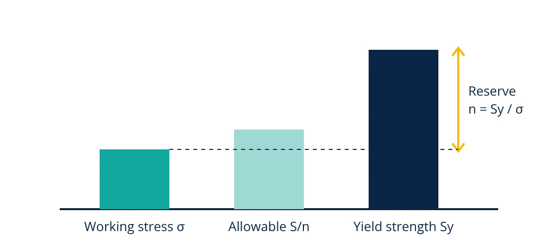
The factor of safety (FoS or n) is the ratio of the strength of a part to the stress it actually carries: n = strength / working stress. A value of 2 means the part could take twice its working stress before it fails. Ductile parts usually use yield strength in the ratio; brittle parts use ultimate strength.
Every machine part is designed with some reserve. Loads are never known exactly, material strength varies from batch to batch, and analysis methods carry simplifications. The factor of safety is the number that covers these uncertainties. Choosing it well is one of the most important judgements in machine design: too low risks failure, too high wastes material and weight.
Factor of safety definition and formula
The factor of safety compares a failure quantity with the corresponding working quantity:
S is the relevant strength of the material and σ is the calculated stress at the critical point. The load form is used when stress and load are proportional, as in most linear elastic problems.
The strength used depends on how the part fails:
- Ductile materials (steel, aluminium): failure is taken as yielding, so n = Sy / σ. Permanent deformation usually makes a machine part useless even before it breaks.
- Brittle materials (cast iron, some ceramics): there is little yielding, so n = Sut / σ, using ultimate tensile strength.
- Fatigue: for fluctuating loads the endurance limit or fatigue strength replaces static strength.
- Buckling: for slender columns the critical buckling load replaces the strength.
The allowable stress (also called permissible or design stress) follows directly: σallow = S / n. Designers often fix n first, compute σallow and then size the part so its stress stays below that value.
What the factor of safety covers
A factor of safety is not a fudge factor. It deliberately covers known sources of uncertainty:
- Load uncertainty: overloads, shock, starting torque, misuse and dynamic effects that the nominal load does not include.
- Material variability: published strengths are minimum or typical values; actual parts vary with heat treatment, size and supplier.
- Manufacturing: dimensional tolerances, surface finish, residual stresses and weld quality.
- Analysis simplifications: idealised supports, neglected stress concentrations, assumed load distribution.
- Environment and time: corrosion, wear, temperature and creep reduce strength during service.
- Consequence of failure: a failure that could injure people or cause large losses justifies a larger margin.
Better information allows a smaller factor. A part whose loads are measured, whose material is certified and whose stresses are checked by test or finite element analysis can be designed closer to the limit than one based on rough estimates.
Typical factor of safety values
The ranges below are commonly quoted in machine design textbooks as starting points. Where a code or standard applies, its requirement governs.
| Situation | Typical factor of safety |
|---|---|
| Reliable materials, well known loads, ductile part (on yield) | 1.25 to 1.5 |
| Average materials and loads, ordinary machine parts (on yield) | 1.5 to 2 |
| Less certain loads or material data | 2 to 3 |
| Brittle materials (on ultimate strength) | 3 to 4 or more |
| Shock or impact loads, untested materials | 3 to 5 or more |
Aircraft structures may use about 1.5 on ultimate load because weight is critical and testing is extensive. Lifting gear such as wire ropes and chains often uses 4 to 6 or more, set by the relevant lifting standard, because failure is dangerous and wear reduces strength.
- Given
- A solid circular steel link carries a steady tensile load of 25 kN. Material yield strength Sy = 250 MPa. Required factor of safety on yield n = 2.5.
- Find
- The minimum diameter of the link, then the actual factor of safety if a 20 mm bar is used.
- Assumptions
- Static load through the centroid, no stress concentration in the plain section, ductile material.
- Solution
- Allowable stress σallow = Sy / n = 250 / 2.5 = 100 MPa
Required area A = F / σallow = 25,000 / 100 = 250 mm²
d = √(4A / π) = √(4 × 250 / 3.1416) = 17.8 mm
With d = 20 mm: A = 314.2 mm², σ = 25,000 / 314.2 = 79.6 MPa
n = 250 / 79.6 = 3.14 - Answer
- Minimum diameter 17.8 mm; a standard 20 mm bar gives an actual factor of safety of about 3.1
- Limitations
- End connections, holes or threads raise local stress and must be checked separately. Fluctuating loads need a fatigue check.
How to choose a factor of safety
- Check for a governing code. Pressure vessels, cranes, lifts, structures and aircraft have mandatory rules. Follow them first.
- Identify the failure mode. Yield, fracture, fatigue, buckling, wear and excessive deflection each need their own check and margin.
- Assess the uncertainty in each input. Loads, material properties, stress analysis and environment.
- Consider the consequence of failure. Higher risk to people or production means a higher factor.
- Balance against cost and weight. In vehicles and aircraft, every extra kilogram matters, so uncertainty is reduced by testing rather than by large factors.
Some designers split the factor into partial factors, one on load and one on material, as structural design codes do. This makes it clear where the margin comes from.
Factor of safety in practice
- Shafts and keys: combined bending and torsion stresses are compared with yield using a failure theory such as maximum shear stress or distortion energy, then the factor of safety is applied.
- Bolts: the proof load and the joint preload set the margin against yield and joint separation.
- Bearings: a rating life approach is used instead; bearing life depends strongly on lubrication.
- Pump and compressor parts: casings are checked for pressure and impellers for centrifugal stress; see the centrifugal pump working principle.
Common mistakes
- Applying the factor twice, once to the load and again to the strength, which leads to oversized parts.
- Using ultimate strength for a ductile part where yielding is already a failure.
- Checking only static strength when the load fluctuates and fatigue governs.
- Treating a large factor of safety as a substitute for understanding the loads.
Related reading
Frequently asked questions
What is a good factor of safety?
There is no single value. Ductile parts with well known loads and materials are often designed with 1.5 to 2 on yield. Uncertain loads, brittle materials, shock or fatigue push the value to 3 or more. Codes such as pressure vessel and lifting equipment standards set mandatory minimum factors.
What is the difference between factor of safety and margin of safety?
Factor of safety is failure load divided by working load. Margin of safety is that factor minus one. A factor of safety of 1.5 equals a margin of safety of 0.5, meaning the part can carry 50 percent more than the working load before failure.
Can the factor of safety be less than 1?
A calculated value below 1 means the predicted stress exceeds the strength, so failure is expected. The design must be changed by increasing size, choosing a stronger material or reducing the load.
Is design factor the same as factor of safety?
They are closely related. The design factor is the target chosen at the start of design. The factor of safety is what the finished design actually achieves after the real size and strength are known, and it should be equal to or greater than the design factor.
References
- R. G. Budynas and J. K. Nisbett, Shigley's Mechanical Engineering Design, 11th ed., McGraw-Hill
- R. L. Norton, Machine Design: An Integrated Approach, 6th ed., Pearson
- V. B. Bhandari, Design of Machine Elements, 4th ed., McGraw-Hill Education
- ASME Boiler and Pressure Vessel Code, Section VIII, Division 1
Get one engineering email a week
New articles, worked examples and study notes every week. Free, no spam, unsubscribe any time.