Types of Gears and Their Applications
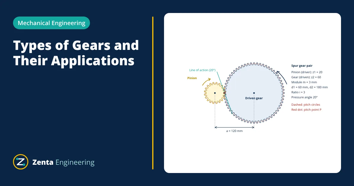
The main types of gears are spur, helical and herringbone gears for parallel shafts, bevel gears for intersecting shafts, and worm, hypoid and crossed helical gears for shafts that neither meet nor run parallel. A rack and pinion turns rotation into straight line motion. The choice depends on the shaft layout, the speed ratio, the load, the noise allowed and the efficiency needed.
Gears transmit motion and torque between shafts through meshing teeth. Unlike belts, they give a fixed speed ratio with no slip, they carry high loads in a small space and they can change the direction of rotation. They appear in machine tools, vehicle transmissions, tractor drivelines, wind turbines, pumps and clocks.
Gear terms you need first
The terms below follow ANSI/AGMA 1012 and the textbooks by Budynas and Nisbett (Shigley) and Norton.
- Pitch circle: an imaginary circle on which two meshing gears roll without slipping. Its diameter is the pitch diameter d.
- Number of teeth z and module m: in metric practice d = m z. The module is the size of the teeth in millimetres. ISO 54 lists the preferred module values.
- Pressure angle: the angle between the line of action and the common tangent to the pitch circles. ISO 53 specifies a basic rack with a 20 degree pressure angle.
- Gear ratio: i = z2 / z1 = n1 / n2, where n is speed. The small gear is the pinion.
- Centre distance: a = m (z1 + z2) / 2 for a standard external spur pair.
The teeth of almost all power gears have an involute profile. An involute tooth keeps a constant velocity ratio even if the centre distance changes slightly, which is why it is the standard form.
Types of gears by shaft arrangement
Parallel shafts
Spur gears have straight teeth parallel to the shaft axis. They are the simplest to make and inspect, produce no axial thrust and are very efficient. Their drawback is noise at high speed, because each tooth picks up its load suddenly. They suit gearboxes, pumps, machine tools and moderate speed drives.
Helical gears have teeth cut at a helix angle to the axis. Contact starts at one end of the tooth and spreads across the face, so the load is shared by more teeth and the mesh is quieter and smoother. The helix angle produces an axial thrust that the bearings must carry. Helical gears are standard in automotive gearboxes and industrial speed reducers.
Double helical and herringbone gears have two sets of opposite hand helical teeth side by side. The axial thrust of one half cancels the other, so heavy loads can be carried without large thrust bearings. They are used in large turbine reduction gears, rolling mills and heavy marine drives.
Internal gears have teeth on the inside of a ring. An internal pair rotates in the same direction and gives a compact layout, which is why internal gears form the ring of planetary gear trains.
Rack and pinion
A rack is a gear of infinite radius: a straight bar with teeth. A pinion meshing with it converts rotation into linear motion, with travel per revolution equal to π d. Examples are vehicle steering, machine tool slides and linear actuators.
Intersecting shafts
Bevel gears are cut on cones and connect shafts whose axes meet, usually at 90 degrees. Straight bevel gears have straight teeth and suit low speeds. Spiral bevel gears have curved, inclined teeth that engage gradually, giving quieter running at higher speeds. A pair of equal bevel gears at 90 degrees is a mitre gear set. Bevel gears are used in differentials, hand drills and right angle gearboxes.
Non-parallel, non-intersecting shafts
Hypoid gears look like spiral bevel gears, but the pinion axis is offset from the gear axis. The offset allows a larger, stronger pinion and lets a vehicle’s drive shaft sit lower. The teeth slide more than in bevel gears, so hypoid sets need extreme pressure lubricants, as discussed in types of lubrication.
Worm gears consist of a screw (the worm) meshing with a worm wheel, normally with shafts at 90 degrees. A single start worm advances the wheel by one tooth per revolution, so very high ratios are possible in one stage. The thread slides across the wheel teeth, so efficiency is lower than for other types and heat must be removed. Small lead angles can make the drive self-locking. Worms are usually hardened steel and wheels are often bronze to reduce friction and wear.
Crossed helical gears are two helical gears on non-parallel shafts. Contact is ideally at a point, so they carry only light loads, for example in instrument drives.
Comparison of the main types of gears
| Type | Shaft layout | Typical single stage ratio | Noise | Notes |
|---|---|---|---|---|
| Spur | Parallel | Low to moderate | Highest | Simple, no axial thrust, high efficiency |
| Helical | Parallel | Low to moderate | Low | Axial thrust, smooth at high speed |
| Herringbone | Parallel | Low to moderate | Low | Thrust cancels, heavy loads |
| Bevel | Intersecting | Low to moderate | Medium (straight), low (spiral) | Right angle drives, differentials |
| Hypoid | Offset, non-intersecting | Moderate | Low | Needs EP lubricant, vehicle axles |
| Worm | Non-intersecting, usually 90° | High | Low | Sliding contact, lower efficiency, can self-lock |
| Rack and pinion | Rotary to linear | Not applicable | Medium | Steering, slides, actuators |
Worked example: spur gear ratio, speed and forces
- Given
- A spur pinion with z1 = 20 teeth drives a gear with z2 = 60 teeth. Module m = 3 mm, pressure angle 20°. The pinion is driven by a 5 kW motor at 1440 rpm.
- Find
- Pitch diameters, centre distance, gear ratio, output speed, pinion and output torque, tangential and radial tooth forces.
- Assumptions
- Standard involute teeth with no profile shift; friction and bearing losses neglected, so output power equals input power.
- Solution
- d1 = 3 × 20 = 60 mm; d2 = 3 × 60 = 180 mm
a = (60 + 180) / 2 = 120 mm
i = 60 / 20 = 3; n2 = 1440 / 3 = 480 rpm
T1 = P / ω = 5000 / (2π × 1440 / 60) = 33.2 N·m
T2 = 33.2 × 3 = 99.5 N·m
Ft = 2 T1 / d1 = 2 × 33.16 / 0.060 = 1105 N
Fr = Ft × tan 20° = 1105 × 0.364 = 402 N - Answer
- d1 = 60 mm, d2 = 180 mm, a = 120 mm, i = 3, n2 = 480 rpm, T2 about 99.5 N·m, Ft about 1105 N, Fr about 402 N
- Limitations
- Real meshes have small losses, so output torque is slightly lower. Tooth bending and contact stresses must still be checked with the AGMA or ISO 6336 methods, including dynamic and load distribution factors.
The tangential force is what transmits torque and bends the teeth. The radial force pushes the gears apart and is carried, together with the tangential force, by the shaft bearings. Gear teeth carry repeated load cycles, so their design also has to consider fatigue failure and a suitable factor of safety.
How to choose among the types of gears
- Shaft layout first. Parallel shafts point to spur or helical gears; intersecting shafts to bevel gears; offset crossing shafts to worm or hypoid gears.
- Ratio. If a very high reduction is needed in one stage, consider a worm drive or a planetary train. Otherwise use several spur or helical stages.
- Speed and noise. For high pitch line speeds or quiet operation, choose helical or spiral bevel teeth.
- Efficiency and heat. Where energy cost or heat matters, avoid worm drives with low lead angles.
- Thrust loads. Helical and bevel gears create axial loads that the bearings must take; herringbone gears avoid this.
- Cost and manufacture. Spur gears are cheapest to cut and inspect; hypoid and spiral bevel sets need specialised machines.
Gear materials and lubrication
Most power gears are made of steel, often case hardened or through hardened, as Budynas and Nisbett describe. Cast iron is used for large, lightly loaded gears and gives good damping. Bronze is common for worm wheels. Plastics such as nylon and acetal serve quiet, light duty drives. Correct lubrication, either splash, oil jet or grease, controls wear and removes heat, especially in worm and hypoid sets.
Related reading
Frequently asked questions
Which type of gear is the most efficient?
Spur and helical gears on parallel shafts are the most efficient because the teeth mainly roll with only a small amount of sliding. Worm gears have the lowest efficiency of the common types because the worm thread slides across the wheel teeth, and their efficiency falls as the lead angle gets smaller.
Why are helical gears quieter than spur gears?
On a spur gear each tooth makes contact across its whole face width at once, so load is applied and removed suddenly. On a helical gear the inclined teeth come into contact gradually from one end of the face to the other, and more than one pair of teeth share the load. This smoother transfer of load reduces noise and vibration.
What does self-locking mean in a worm gear?
A self-locking worm drive cannot be driven backwards from the wheel, because friction at the thread is high enough to stop the wheel turning the worm. It happens when the lead angle is small relative to the friction angle. It is useful in hoists and lifts, but designers should not rely on it alone as a safety brake, because vibration can reduce friction.
References
- R. G. Budynas and J. K. Nisbett, Shigley's Mechanical Engineering Design, 11th ed., McGraw-Hill, 2020
- R. L. Norton, Machine Design: An Integrated Approach, 6th ed., Pearson, 2020
- S. P. Radzevich, Dudley's Handbook of Practical Gear Design and Manufacture, 3rd ed., CRC Press, 2016
- ISO 53:1998 Cylindrical gears for general and heavy engineering, Standard basic rack tooth profile
- ISO 54:1996 Cylindrical gears for general engineering and for heavy engineering, Modules
- ANSI/AGMA 1012-G05 Gear Nomenclature, Definitions of Terms with Symbols
Get one engineering email a week
New articles, worked examples and study notes every week. Free, no spam, unsubscribe any time.

