Tractor Power Transmission System Explained
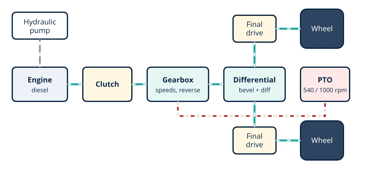
Tractor power transmission is the system of clutch, gearbox, differential and final drive that carries power from the diesel engine to the rear wheels, reducing high engine speed to the low speed and high torque needed for field work. A separate path drives the power take-off shaft at 540 or 1000 rpm and the hydraulic pump.
A tractor engine produces its best power at around 1800 to 2200 rpm, but the rear wheels must turn at only about 10 to 60 rpm in the field, while delivering enormous torque to pull a plough. The transmission system makes this possible and also lets the tractor run implements, reverse, turn corners without wheel scrubbing and travel on roads at 30 to 50 km/h.
Main components of the tractor power transmission
1. Clutch
The clutch connects and disconnects the engine from the transmission so the driver can start smoothly, change gears and stop without stalling. Most tractors use dry friction plate clutches or wet multi-plate clutches running in oil. A dual clutch on many tractors has one stage for the transmission and a second for the PTO, so the PTO can keep running while the tractor stops, which is useful for implements such as balers. Independent PTO clutches go further, controlling the PTO separately.
2. Gearbox (transmission)
The gearbox provides several speed ratios and reverse:
- Sliding mesh and constant mesh: simple, robust; the tractor must stop to change gear.
- Synchromesh: synchronisers match speeds so gears can be changed while moving.
- High-low range and creeper gears: multiply the number of ratios; creeper gears give very slow speeds for transplanting and trenching.
- Powershift: hydraulically engaged clutch packs change gears under load without using the main clutch.
- Hydrostatic transmission (HST): an engine driven hydraulic pump drives hydraulic motors, giving infinitely variable speed and easy direction changes; common in small tractors and loaders.
- Continuously variable transmission (CVT): combines hydrostatic and mechanical paths for stepless speed with high efficiency; used in premium tractors.
3. Differential
A bevel pinion and crown wheel turn the drive through 90° and give a reduction. The differential gears allow the left and right wheels to rotate at different speeds when turning. The differential lock forces equal speeds when one wheel slips. Tractors also have independent rear brakes on each side to help tight turns.
4. Final drive
A final gear reduction, often a planetary (epicyclic) gear set at each wheel hub or a spur gear reduction, multiplies torque again just before the wheels. This keeps torque in the gearbox and differential lower, reducing their size.
5. Wheels and tyres
Large rear tyres with deep lugs provide traction. Four wheel drive tractors also drive the front wheels through a transfer case and front axle, improving traction by around 10 to 20% in the field. Wheel slip of about 8 to 15% gives the best tractive efficiency on most soils.
6. Power take-off and hydraulics
The PTO shaft delivers power to implements at standard speeds defined by ISO 500: 540 rpm (6 spline, 35 mm) and 1000 rpm (21 spline, 35 mm, or 20 spline, 44 mm). PTO shafts must always be guarded, because entanglement causes many serious farm injuries. The hydraulic system powers the three point linkage, draft control and remote cylinders.
Overall gear ratio and speed
Total reduction is the product of gearbox, bevel and final drive ratios:
where v is in km/h, N in rpm and D in metres (neglecting slip). Wheel torque is engine torque times total ratio times efficiency.
- Given
- A tractor engine runs at 2000 rpm and produces 250 N·m. In third gear the gearbox ratio is 4.0, the bevel ratio 4.5 and the final drive ratio 5.0. Rear tyre rolling diameter is 1.5 m. Transmission efficiency is 88%.
- Find
- Total ratio, theoretical ground speed and total torque at the rear wheels.
- Assumptions
- No wheel slip; torque shared between both rear wheels.
- Solution
- i_total = 4.0 × 4.5 × 5.0 = 90
Wheel speed = 2000 ÷ 90 = 22.2 rpm
v = 22.2 × π × 1.5 × 60 ÷ 1000 = 6.28 km/h
Wheel torque = 250 × 90 × 0.88 = 19 800 N·m (total for both wheels) - Answer
- Total ratio 90, ground speed about 6.3 km/h, and about 19.8 kN·m of axle torque, suitable for ploughing
- Limitations
- Wheel slip of around 10% would reduce actual speed to about 5.7 km/h.
Key formulas for tractor power transmission
| Quantity | Formula | Symbols and units |
|---|---|---|
| Total gear ratio | i_total = i_gear × i_bevel × i_final | i_gear, i_bevel, i_final = gearbox, bevel and final drive ratios (dimensionless) |
| Ground speed | v = (N_engine ÷ i_total) × π D_wheel × 60 ÷ 1000 | v in km/h, N_engine in rpm, D_wheel = rolling diameter in m, slip neglected |
| Wheel torque | T_wheel = T_engine × i_total × η | T in N·m, η = transmission efficiency |
Matching tractor and implement
Choosing the right gear for each job keeps the engine near its best operating point. For heavy drawbar work such as ploughing, the tractor should run at a speed where wheel slip stays around 8 to 15% and the engine is loaded close to its rated power. For light PTO work such as spraying, using the economy PTO setting lets the engine run slower, saving fuel. Ballast, tyre size and four wheel drive engagement also affect how well transmission power converts into useful pull.
Maintenance of the transmission
- Check and change transmission and hydraulic oil at the intervals in the operator’s manual, using the specified grade, as many tractors share oil between gearbox, differential and hydraulics. See types of lubrication.
- Adjust clutch free play to prevent slipping and wear.
- Inspect PTO shaft guards and universal joints.
- Avoid shock loads from engaging the clutch or PTO at high engine speed.
- Use the correct ballast and tyre pressures to balance traction and soil compaction.
Trends in tractor power transmission
Modern tractors increasingly use electronically controlled powershift and CVT transmissions linked to engine management, so the tractor automatically keeps the engine at the most efficient speed for the load. Combined with GPS guidance and precision agriculture technologies, this improves fuel efficiency and productivity. Electric and hybrid drivelines are emerging for small tractors and for implements driven by electric motors instead of mechanical PTO shafts.
Tractor power transmission interview and viva questions
- Why does a tractor need such a large total gear reduction? The engine gives its best power at around 1800 to 2200 rpm, but the rear wheels must turn at only about 10 to 60 rpm in the field. The gearbox, bevel gear and final drive cut the speed and multiply the torque.
- What is the purpose of a dual clutch? One stage controls the transmission and the second controls the PTO, so the PTO can keep running while the tractor stops, which suits implements such as balers.
- Why is a final drive reduction placed just before the wheels? Making the last torque multiplication at the wheels keeps torque in the gearbox and differential lower, which reduces their size.
- What are the standard PTO speeds? ISO 500 defines 540 rpm with a 6 spline, 35 mm shaft and 1000 rpm with a 21 spline, 35 mm or a 20 spline, 44 mm shaft.
- How does a hydrostatic transmission differ from a CVT? A hydrostatic transmission uses an engine driven hydraulic pump and hydraulic motors for infinitely variable speed, while a CVT combines hydrostatic and mechanical paths for stepless speed with higher efficiency.
Frequently asked questions
What is the PTO on a tractor?
The power take-off is a splined shaft, usually at the rear, that delivers engine power directly to implements such as rotavators, mowers, balers and pumps. Standard speeds are 540 and 1000 rpm, defined in ISO 500, with economy settings that reach those speeds at lower engine rpm to save fuel.
Why do tractors have so many gears?
Tractors work at very different speeds: slow for heavy tillage and transplanting, moderate for ploughing and harvesting, and fast for road transport. Many gear ratios let the engine run near its best power or fuel efficiency at each ground speed and load. Range, high-low and creeper gears multiply the number of speeds.
What does the differential lock do?
The differential normally lets the rear wheels turn at different speeds when cornering. In soft or wet soil, one wheel can slip and spin while the other stops. The differential lock forces both wheels to turn together, restoring traction. It must be released before turning to avoid damage and steering difficulty.
References
- J. B. Liljedahl, P. K. Turnquist, D. W. Smith and M. Hoki, Tractors and Their Power Units, 4th ed., ASABE
- ISO 500-1:2014, Agricultural tractors: Rear-mounted power take-off types 1, 2, 3 and 4
- OECD Standard Codes for the Official Testing of Agricultural and Forestry Tractors, 2024
- D. Renius, Fundamentals of Tractor Design, Springer, 2020
Get one engineering email a week
New articles, worked examples and study notes every week. Free, no spam, unsubscribe any time.