Bernoulli Equation: Derivation, Assumptions and Applications
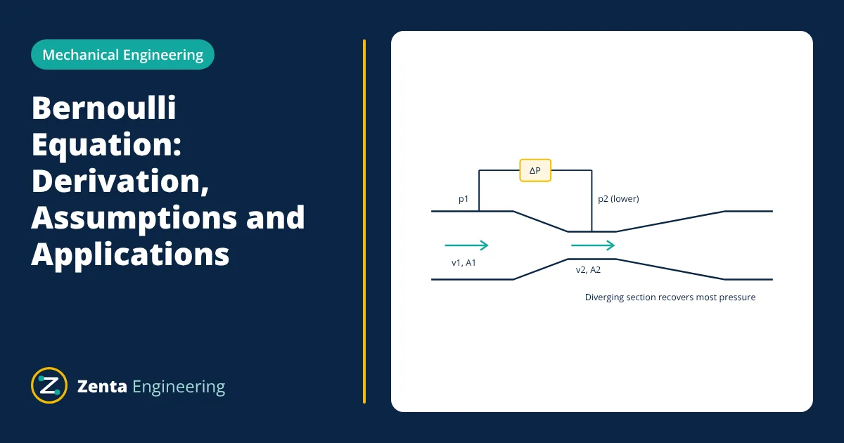
The Bernoulli equation says that for steady, incompressible, frictionless flow along a streamline, pressure energy plus kinetic energy plus potential energy is constant: p + ½ρv² + ρgz = constant. Where the fluid speeds up, its pressure falls. It is the basis of venturi meters, pitot tubes, orifice plates and many pipe flow calculations.
The Bernoulli equation is the most used result in fluid mechanics. It links the pressure, velocity and height of a moving fluid with one simple expression. It explains why water speeds up through a nozzle, how a differential pressure flowmeter works and how much pressure a pump must add to lift water. Used carelessly, it also gives wrong answers, so its assumptions matter as much as the formula.
The Bernoulli equation
Between two points 1 and 2 on the same streamline:
where p is static pressure (Pa), ρ is density (kg/m³), v is velocity (m/s), g is 9.81 m/s² and z is elevation (m). Each term is an energy per unit volume, so each has units of pressure.
Dividing by ρg gives the head form used by pump and piping engineers, where every term is a height of fluid in metres:
- Pressure head p / ρg: the height of fluid column the pressure could support. The hydrostatic pressure formula p = ρgh is the same relation at rest.
- Velocity head v² / 2g: the kinetic energy per unit weight.
- Elevation head z: potential energy per unit weight above a datum.
The sum H is the total head. Static pressure plus ½ρv² is called stagnation pressure, the pressure measured where the flow is brought to rest.
Simple derivation from energy
Consider a small slug of fluid of mass m and volume V moving through a pipe from section 1 to section 2 in steady flow. The pressure at section 1 pushes the fluid in and does work p₁V on it. At section 2 the fluid downstream resists with pressure p₂ and the slug does work p₂V. With no friction and no heat transfer, the net work equals the gain in kinetic and potential energy:
Dividing by V and using m / V = ρ gives the Bernoulli equation. The same result follows from applying Newton’s second law along a streamline (Euler’s equation) and integrating, or from the steady flow energy equation of the first law of thermodynamics for an incompressible fluid with no heat transfer and no shaft work.
Assumptions and limits
The simple form holds only when all of these are reasonable:
- Steady flow: conditions at a point do not change with time.
- Incompressible fluid: density constant. Liquids qualify; gases qualify below about Mach 0.3.
- Frictionless (inviscid) flow: no viscous losses between the two points.
- Along a streamline: the two points lie on the same streamline (or the flow is irrotational).
- No machines or heat transfer: no pump, fan or turbine between the points, and no heating.
Real pipelines violate assumption 3, so engineers use the extended energy equation, adding pump head and subtracting friction and fitting losses:
The head loss hL is found from the Darcy-Weisbach equation and loss coefficients for valves and fittings. This form is used to size pumps; see the centrifugal pump working principle.
Venturi meter: the Bernoulli equation at work
A venturi narrows the pipe to a throat and then widens it gradually. Continuity (Q = A₁v₁ = A₂v₂) says velocity rises in the throat, and Bernoulli says pressure falls. Measuring that pressure difference gives the flow rate.
Combining continuity with Bernoulli for a horizontal venturi gives the ideal flow rate:
Real meters multiply this by a discharge coefficient Cd (about 0.98 to 0.99 for a classical venturi under ISO 5167-4) to account for friction. Orifice plates use the same principle with a lower Cd. Flow increases with the square root of differential pressure, which is why DP transmitters apply square root extraction.
- Given
- Water (ρ = 1000 kg/m³) flows through a horizontal venturi with inlet diameter 100 mm and throat diameter 50 mm. The measured differential pressure is 20 kPa.
- Find
- The ideal flow rate and the throat velocity.
- Assumptions
- Steady, incompressible, frictionless flow; uniform velocity at each section; horizontal meter so z₁ = z₂.
- Solution
- A₁ = π × 0.1² / 4 = 0.007854 m²; A₂ = π × 0.05² / 4 = 0.001963 m²
(A₂/A₁)² = 0.25² = 0.0625
v₂ = √(2 × 20,000 / (1000 × (1 − 0.0625))) = √42.67 = 6.53 m/s
Q = A₂ × v₂ = 0.001963 × 6.53 = 0.01282 m³/s - Answer
- Ideal flow about 0.0128 m³/s (46 m³/h); throat velocity 6.5 m/s
- Limitations
- Multiply by the discharge coefficient (about 0.98) for the real flow. Check that throat pressure stays above vapour pressure to avoid cavitation.
Other applications
- Pitot tube: measures stagnation minus static pressure, giving velocity v = √(2Δp / ρ). Used in ducts and on aircraft.
- Flow from a tank (Torricelli): a jet leaving an orifice at depth h has velocity √(2gh), before losses.
- Siphons and suction lines: low pressure at high points can drop below vapour pressure, causing cavitation.
- Spray nozzles and ejectors: high velocity creates low pressure that draws in a second fluid.
The flow rate formula Q = A × v, together with the Bernoulli equation, solves most basic flow problems.
Energy and hydraulic grade lines
Piping engineers often draw the Bernoulli equation as two lines along a pipe. The energy grade line plots total head H; the hydraulic grade line plots pressure head plus elevation, which is what a piezometer tube would show. The gap between them is the velocity head. Without friction the energy grade line is horizontal. In a real pipe it slopes down in the flow direction because of friction, jumps up at a pump and drops at valves and fittings. If the hydraulic grade line falls below the pipe itself, the pressure there is below atmospheric.
Common mistakes
- Applying it across a pump or a partly closed valve without adding pump head or losses.
- Mixing gauge and absolute pressures between the two points.
- Using it for high speed gas flow where density changes.
- Forgetting that friction makes the downstream total head lower, never higher.
Related reading
Frequently asked questions
What does the Bernoulli equation state?
Along a streamline in steady, incompressible, frictionless flow, the sum of pressure energy, kinetic energy and potential energy per unit volume stays constant. When velocity rises, pressure or elevation must fall, and the reverse.
Can the Bernoulli equation be used for real pipe flow?
Yes, if friction and fittings are accounted for. The extended energy equation adds a head loss term for friction and minor losses, and pump or turbine head terms where machines add or remove energy.
Why does pressure drop in a venturi throat?
The same volume flow must pass through a smaller area, so velocity rises. With no energy added, the extra kinetic energy comes from pressure energy, so static pressure falls in the throat. Measuring that drop gives the flow rate.
Is the Bernoulli equation valid for gases?
It can be used for gases when density changes are small, which is usually true below a Mach number of about 0.3. At higher speeds compressible flow equations are needed.
References
- F. M. White, Fluid Mechanics, 8th ed., McGraw-Hill
- Y. A. Cengel and J. M. Cimbala, Fluid Mechanics: Fundamentals and Applications, 4th ed., McGraw-Hill
- R. W. Fox, A. T. McDonald and J. W. Mitchell, Introduction to Fluid Mechanics, 10th ed., Wiley
- ISO 5167-4:2022 Measurement of fluid flow by means of pressure differential devices, Part 4: Venturi tubes
Get one engineering email a week
New articles, worked examples and study notes every week. Free, no spam, unsubscribe any time.

