Ship Electrical Power System Layout
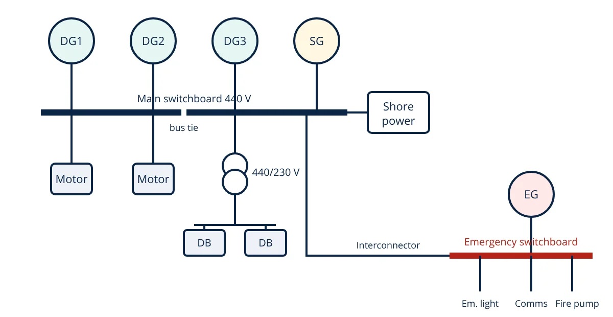
A ship electrical power system generates, distributes and protects electrical power on board. Typically, two to four diesel generators (and sometimes a shaft generator) feed a main switchboard at 440 V or 690 V, 60 Hz, three phase (or 6.6 kV and 11 kV on large ships). The main switchboard supplies large motors directly and feeds distribution boards and transformers for 230 V lighting and small loads. An emergency generator and emergency switchboard, outside the machinery space, power essential services if the main supply fails. Ships usually use an insulated neutral system with earth fault monitoring, and can connect to shore power in port.
A modern ship is an isolated power station. It must supply propulsion auxiliaries, steering, navigation, cargo handling, refrigeration, accommodation and safety systems at sea for weeks, with no grid to fall back on. Reliability, redundancy and safety are designed in at every level, guided by SOLAS, classification society rules and the IEC 60092 standards.
Typical layout
Generation
- Diesel generators (DG): usually three or four medium or high speed diesel engines driving alternators. Several units allow one to be shut down for maintenance while others carry the load with spare capacity.
- Shaft generator (SG): driven by the main engine, often through a power take-off gear, producing cheaper electricity at sea.
- Turbo generators on ships with large exhaust gas boilers, and battery systems on hybrid vessels.
- Emergency generator (EG): an independent diesel generator above the bulkhead deck with its own fuel tank, starting automatically on blackout.
Main switchboard
The main switchboard collects generator output and distributes it. It contains air circuit breakers for each generator with protection relays, synchronising equipment, bus tie breakers splitting the board into two sections for redundancy, feeders for large consumers and section boards, power management system controls, metering and the earth fault monitor. Switchboard protection devices follow the same principles as on land, see circuit breaker working principle and overcurrent relay.
Distribution
- 440 V or 690 V: large motors such as pumps, compressors, fans, cranes and bow thrusters.
- Transformers step down to 230 V or 115 V for lighting, galley, sockets and small equipment, as described in transformer working principle.
- Section and distribution boards around the ship.
- 24 V DC systems with batteries for alarms, communications, navigation and emergency lighting backup.
Emergency power
SOLAS requires a self-contained emergency source capable of supplying essential services: emergency lighting, navigation lights, radio and internal communications, fire detection and alarms, emergency fire pump, watertight doors, and others. A transitional source (batteries or UPS) covers the gap until the emergency generator starts, within 45 seconds.
Insulated neutral system and earth faults
Most low voltage ship systems are insulated neutral (IT): the generator star point is not connected to the hull. A single earth fault does not trip supplies, keeping essential services running, while the earth fault monitor alarms. Insulation must be maintained high; engineers test with insulation resistance testers, as in the insulation resistance test. High voltage ship systems often use high resistance earthing to limit fault current while allowing selective protection.
Power management and load sharing
When generators run in parallel, they must be synchronised before connecting (matching voltage, frequency and phase) and must share load:
- Active power (kW) sharing is set by governors with speed droop.
- Reactive power (kVAR) sharing is set by automatic voltage regulators.
A power management system (PMS) starts and stops generators according to load, prevents blackouts by starting standby sets and blocking large motor starts until capacity is available, and performs preferential tripping of non-essential loads on overload.
- Given
- A ship has three 900 kW diesel generators at 440 V, 60 Hz, power factor 0.8. At sea the load is 1250 kW. A 300 kW ballast pump motor is to be started.
- Find
- Generator loading with two sets running, whether the pump can be started on two sets with a 85% maximum loading limit, and the current per generator.
- Assumptions
- Equal load sharing; starting surge handled by spare capacity; three phase current I = P ÷ (√3 × V × pf).
- Solution
- Two sets: capacity 1800 kW; load 1250 kW = 69%
After pump: 1550 kW = 86%, above the 85% limit, so the PMS should start the third generator first
Three sets: 1550 ÷ 2700 = 57%
Current per generator = (1550 ÷ 3) × 1000 ÷ (1.732 × 440 × 0.8) = 516 700 ÷ 609.7 ≈ 847 A - Answer
- Start the third generator before the ballast pump; with three sets the load is 57%, about 850 A per generator
- Limitations
- Direct online motor starting draws several times rated current; soft starters or VFDs reduce the dip.
Blackout and recovery
A blackout happens when all generators trip, for example from a fuel problem, governor fault or overload. The emergency generator starts automatically and restores essential services, while the power management system or engineers restart main generators, close breakers onto the dead bus, and restart essential auxiliaries in sequence so the main engine can run again. Blackout recovery is practised in drills because loss of propulsion near a coast or in heavy traffic is very dangerous.
Electric propulsion and hybrid ships
Cruise ships, offshore vessels, icebreakers and LNG carriers often use diesel electric propulsion: generators feed a high voltage switchboard and large variable frequency drives power propulsion motors. This allows flexible engine loading and redundancy. Battery hybrid ships store energy for peak shaving, spinning reserve and zero emission port operations, similar to battery energy storage systems on land.
Shore power and safety of the ship electrical power system
Shore power (cold ironing) lets ships switch off generators in port, reducing emissions and noise, with high voltage shore connections standardised in IEC/IEEE 80005-1. Electrical safety on board covers enclosure ratings for wet and hazardous areas, cable selection under IEC 60092, regular insulation tests, safe isolation procedures and battery room ventilation. A well designed ship electrical power system keeps the vessel powered and safe, from the ship auxiliary machinery in the engine room to the lifesaving and firefighting equipment required by SOLAS.
Frequently asked questions
Why do ships use insulated neutral systems?
In an insulated (unearthed) neutral system, a single earth fault does not cause a short circuit or trip the supply, so essential services such as steering gear and propulsion keep running. The fault is shown by an earth fault monitor, and engineers can locate and fix it. A second fault on another phase would trip, so the first must be cleared promptly.
What does the emergency generator supply?
The emergency generator, located above the bulkhead deck outside the machinery space, must start automatically and supply essential services within 45 seconds of a main power failure. These include emergency lighting, navigation lights, communications, fire detection and alarms, fire pump, steering gear (in some cases) and other services listed in SOLAS Chapter II-1, for 18 hours on cargo ships and 36 hours on passenger ships.
What is a preferential trip?
A preferential trip disconnects non-essential loads such as galley equipment, air conditioning and some pumps when generators become overloaded. This prevents a complete blackout by keeping essential services such as propulsion auxiliaries, steering and navigation running.
References
- SOLAS Chapter II-1, Part D, Electrical installations
- IEC 60092 series, Electrical installations in ships
- H. D. McGeorge, Marine Electrical Equipment and Practice, 2nd ed., Butterworth-Heinemann
- D. T. Hall, Practical Marine Electrical Knowledge, 2nd ed., Witherby
- IEC/IEEE 80005-1, Utility connections in port, High voltage shore connection systems
Get one engineering email a week
New articles, worked examples and study notes every week. Free, no spam, unsubscribe any time.