Insulation Resistance Test (Megger Test) Explained
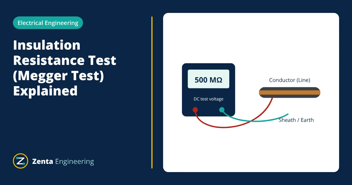
An insulation resistance test (IR test) applies a DC voltage, typically 500 V to 5 kV, between a conductor and earth or between conductors, and measures the small current that flows through the insulation. The tester reports the result as resistance in megohms (MΩ) or gigohms (GΩ). High, rising readings show clean, dry insulation; low or falling readings point to moisture, contamination or damage.
Why the insulation resistance test is done
Insulation in motors, generators, transformers, cables and switchgear degrades with heat, moisture, dirt, vibration and age. An IR test is a simple, non-destructive way to:
- check new installations before they are energised,
- check equipment after repair, flooding or long storage,
- track insulation condition over time in a maintenance programme.
A single reading is useful, but the trend of readings taken under similar conditions is far more informative.
What the tester measures
When a DC voltage is applied across insulation, the total current has three components:
| Current | Cause | Behaviour over time |
|---|---|---|
| Capacitive charging current | Charging the capacitance of the insulation | Falls to almost zero within seconds |
| Absorption (polarisation) current | Alignment of molecules in the insulation material | Decays over minutes |
| Leakage (conduction) current | Current through and across the insulation surface | Stays roughly constant |
The tester divides the test voltage by the total current. As the charging and absorption currents die away, the indicated resistance rises towards a value set by the leakage current. Moisture and contamination increase leakage current, so they keep the reading low and flat.
Choosing the test voltage
The test voltage should stress the insulation without exceeding what it can safely withstand. IEEE 43 recommends DC test voltages for rotating machine windings based on rated voltage:
| Winding rated voltage (V) | Recommended DC test voltage (V) |
|---|---|
| Below 1000 | 500 |
| 1000 to 2500 | 500 to 1000 |
| 2501 to 5000 | 1000 to 2500 |
| 5001 to 12,000 | 2500 to 5000 |
| Above 12,000 | 5000 to 10,000 |
For low voltage installations, IEC 60364-6 specifies the test voltages and minimum values for verification of circuits. Electronic equipment, surge protective devices and drives must be disconnected first, because the test voltage can damage them.
Polarization index and dielectric absorption ratio
Because the reading rises with time, ratios of readings taken at two times are used to judge insulation quality independently of size and temperature:
IEEE 43 recommends a minimum PI of 2.0 for windings with class B, F and H insulation, and 1.5 for class A. A PI close to 1 means the leakage current dominates, which usually indicates moisture or contamination. IEEE 43 also notes that PI is not a meaningful indicator when the 1 minute reading is already above 5000 MΩ.
- Given
- A 415 V motor winding tested at 500 V DC. Reading after 1 minute: 800 MΩ. Reading after 10 minutes: 2400 MΩ.
- Find
- Polarization index and an assessment.
- Assumptions
- Winding clean and at a steady temperature during the test; class F insulation.
- Solution
- PI = 2400 / 800 = 3.0
- Answer
- PI = 3.0, above the IEEE 43 minimum of 2.0, indicating dry, clean insulation
- Limitations
- One test is a snapshot. Compare with earlier results taken at a similar temperature, and investigate any sharp fall even if the value is still above the minimum.
Minimum insulation resistance for machines
IEEE 43 gives recommended minimum 1 minute values, corrected to 40 °C, for rotating machines:
| Winding type | Recommended minimum IR (1 minute, 40 °C) |
|---|---|
| Most AC windings built after about 1970 (form-wound coils) | 100 MΩ |
| Random-wound and form-wound windings rated below 1 kV | 5 MΩ |
| Older windings and some DC windings | kV + 1 MΩ, where kV is the rated voltage in kilovolts |
Effect of temperature
Insulation resistance falls as temperature rises. A common rule of thumb is that it roughly halves for every 10 °C increase, although the exact relationship depends on the material. Readings should therefore be corrected to a reference temperature, such as 40 °C in IEEE 43, before comparing them with limits or earlier results. Humidity also lowers readings, especially through surface leakage.
Keeping useful records
The value of insulation testing comes from comparing results over time. Each record should include the date, equipment identity, test voltage, readings at 30 seconds, 1 minute and 10 minutes where taken, winding or ambient temperature, humidity, the instrument used and the test connections. Plotting temperature-corrected readings for the same machine over several years shows gradual deterioration long before a failure, so repairs can be planned during a shutdown.
Safe test procedure
- Isolate the equipment, lock it off and prove it is dead.
- Disconnect sensitive electronics, surge arresters and capacitors that could be damaged or affect the result.
- Clean and dry terminals to reduce surface leakage.
- Connect the tester: line lead to the conductor, earth lead to the frame or earth. Use the guard terminal to remove surface leakage if needed.
- Apply the test voltage for the required time and record the readings, temperature and humidity.
- After the test, discharge the insulation by earthing it. Large windings and long cables can hold a dangerous charge; IEEE 43 recommends earthing for at least four times the test duration.
Testing cables
Insulation resistance of cables is tested between each core and the other cores connected to earth, and between each core and the armour or screen. Points to remember:
- Length matters. A long cable has more insulation in parallel, so its resistance is lower than a short cable of the same type. Results are sometimes converted to MΩ·km for comparison.
- Capacitance matters. Long cables take time to charge, so readings should be taken after the reading stabilises, and the cable must be discharged afterwards.
- Disconnect both ends. Equipment at either end, such as drives, meters or surge arresters, must be disconnected or the result will reflect that equipment instead of the cable.
For medium and high voltage cables, an IR test is usually followed by withstand tests such as very low frequency (VLF) or DC tests according to the cable standard, and by sheath tests for cables with an outer sheath.
Interpreting results
- High and rising: insulation is in good condition.
- Low but rising: often surface moisture or dirt; cleaning and drying usually help.
- Low and flat or falling: moisture absorbed into the insulation, contamination or damage; investigate before energising.
- Sudden drop between routine tests: a warning sign even if the value is still above the minimum.
Frequently asked questions
Why is it called a Megger test?
Megger is the brand name of an early and widely used insulation resistance tester. The name became a common term for the test, in the same way that a brand can become a generic word. The correct technical term is insulation resistance test.
Is an insulation resistance test the same as a hipot test?
No. An insulation resistance test applies a moderate DC voltage and measures resistance to assess the condition of the insulation. A hipot (high potential) test applies a voltage well above the operating level to prove that the insulation can withstand stress, and is a pass or fail test.
Why do readings rise during the test?
When the DC voltage is first applied, capacitive charging current and absorption current flow in addition to leakage current. These die away over time, so the total current falls and the indicated resistance rises. Clean, dry insulation shows a strong rise.
References
- IEEE 43, IEEE Recommended Practice for Testing Insulation Resistance of Electric Machinery
- IEC 60364-6, Low-voltage electrical installations, Part 6: Verification
- Megger, A Stitch in Time: The Complete Guide to Electrical Insulation Testing
Get one engineering email a week
New articles, worked examples and study notes every week. Free, no spam, unsubscribe any time.
