Electrical Earthing: Purpose, Types and Systems (TN, TT, IT)
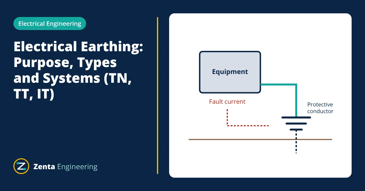
Electrical earthing connects parts of an electrical system to earth so that:
- people are protected from electric shock when insulation fails,
- fault current has a low resistance path, so protective devices trip quickly,
- system voltages stay stable with respect to earth.
IEC 60364 classifies low voltage systems as TN (TN-S, TN-C, TN-C-S), TT and IT, according to how the source and the exposed metal parts are earthed.
Why electrical earthing is needed
If a live conductor touches the metal case of an appliance and the case is not earthed, the case rises to a dangerous voltage. Anyone touching it completes a path to earth through their body. When the case is connected to earth through a protective conductor, the fault current flows through that conductor instead, and it is large enough to operate the fuse, circuit breaker or residual current device (RCD) quickly.
Earthing also:
- limits overvoltages from lightning, switching and contact with higher voltage systems,
- gives a stable reference voltage for the system,
- provides a path for surge protective devices to discharge surges,
- reduces electrical noise in sensitive equipment.
System earthing and equipment earthing
| Type | What is earthed | Purpose |
|---|---|---|
| System (neutral) earthing | The neutral or star point of the source, such as a transformer or generator | Fixes the system voltage to earth and sets the earth fault current level |
| Equipment (protective) earthing | Exposed conductive parts: metal enclosures, frames, cable armour | Prevents dangerous touch voltages and lets protection detect faults |
| Equipotential bonding | Extraneous metal parts: water pipes, gas pipes, structural steel | Keeps all metalwork at the same potential |
The IEC system designations
The letters describe the earthing arrangement:
- First letter (source): T means one point, usually the neutral, is connected directly to earth. I means all live parts are isolated from earth, or one point is earthed through a high impedance.
- Second letter (installation): T means exposed metal parts are connected to a local earth electrode, independent of the source earth. N means exposed metal parts are connected to the earthed point of the source through a protective conductor.
- Further letters (TN only): S means separate neutral (N) and protective (PE) conductors. C means neutral and protective functions are combined in one PEN conductor.
| System | Arrangement | Earth fault path | Typical protection | Typical use |
|---|---|---|---|---|
| TN-S | Separate N and PE from the source to every load | Metallic, low impedance | Fuses, MCBs, MCCBs, plus RCDs where required | Industrial plants, buildings with their own transformer |
| TN-C-S | Combined PEN in the supply network, split into N and PE at the installation | Metallic, low impedance | As TN-S | Many public low voltage networks |
| TN-C | Combined PEN throughout | Metallic, low impedance | Fuses and breakers; RCDs cannot be used on a PEN | Restricted use, mainly older or large fixed installations |
| TT | Source earthed at the supply; installation has its own earth electrode | Through the earth, higher impedance | RCDs | Rural overhead networks, outdoor installations |
| IT | Source isolated or high impedance earthed; exposed parts earthed locally | Very small current on a first fault | Insulation monitoring device, then protection on a second fault | Operating theatres, mines, continuous process plants |
The main advantage of the IT system is continuity: a first earth fault does not cause a trip. The fault must be found and cleared promptly, because a second fault on another phase becomes a short circuit.
Disconnection times
IEC 60364-4-41 sets maximum disconnection times for automatic disconnection of supply. For final circuits up to 32 A on a 230 V system, the limit is 0.4 s in a TN system and 0.2 s in a TT system. To meet these times in a TN system, the earth fault loop impedance must be low enough for the fault current to trip the protective device quickly.
Earth electrodes
An earth electrode makes the connection to the soil. Common types are driven rods, buried plates, horizontal strips and meshes. Their resistance depends mainly on the soil resistivity ρ, which varies widely with soil type, moisture and temperature.
For a single vertical rod of length L and diameter d, a commonly used estimate is:
- Given
- Single rod electrode, length L = 3 m, diameter d = 16 mm, soil resistivity ρ = 100 Ω·m.
- Find
- Approximate earth resistance of the rod.
- Assumptions
- Uniform soil; rod driven vertically with its top at ground level; no nearby electrodes.
- Solution
- 8L / d = 8 × 3 / 0.016 = 1500, and ln(1500) = 7.31
ρ / (2πL) = 100 / (2 × 3.1416 × 3) = 5.31 Ω
R = 5.31 × (7.31 − 1) = 33.5 Ω - Answer
- About 33 Ω
- Limitations
- Real soil is layered and its resistivity changes with season. Rods placed close together interfere, so two rods in parallel come close to half the resistance of one only when they are spaced well apart. Measure the installed resistance with an earth tester.
Ways to lower earth resistance
- Drive rods deeper, where the soil is often moister and more conductive.
- Use several rods in parallel, spaced at least about the rod length apart.
- Use horizontal strips or a buried mesh, especially in rocky ground.
- Improve the soil around the electrode with approved low-resistivity backfill.
Earthing in substations: step and touch voltage
In high voltage substations, earth fault currents can reach tens of kiloamperes. As this current flows into the ground, the soil surface around the earthing system rises in potential, and the potential varies from point to point. Two hazards follow:
- Touch voltage: the voltage between a person’s hand on earthed metalwork and their feet on the ground.
- Step voltage: the voltage between a person’s feet one step apart on the ground.
Substation earthing grids are designed, for example to IEEE 80, so that these voltages stay below tolerable limits for the fault current and clearing time. Designers use a buried mesh of conductors, a surface layer of crushed rock with high resistivity, and bonding of all metal structures and fences. The total grid resistance is usually required to be low, often around 1 Ω or below for large substations, but the step and touch voltage limits are the real design criteria.
Testing and maintenance
Earth electrode resistance is measured with an earth tester, for example by the fall-of-potential method. Earth fault loop impedance is measured at socket outlets and distribution boards to confirm that protective devices will trip in time. Connections should be inspected for corrosion and tightness, because a broken protective conductor removes protection without any visible sign.
Related reading
Frequently asked questions
Is earthing the same as grounding?
Yes. Earthing is the term used in IEC and British practice, and grounding is the North American term. Both mean connecting parts of an electrical system to the general mass of the earth or to a reference conductor.
Why does a TT system usually need an RCD?
In a TT system the fault current returns through the earth, and the earth path resistance is often too high for a fuse or MCB to trip quickly. A residual current device detects small earth leakage currents and disconnects the supply fast enough to protect people.
What is the difference between neutral and earth?
The neutral is a live conductor that carries normal return current. The protective earth conductor carries current only during a fault. In a TN-S system they are joined only at the source.
References
- IEC 60364-4-41, Low-voltage electrical installations, Part 4-41: Protection against electric shock
- IEC 60364-5-54, Low-voltage electrical installations, Part 5-54: Earthing arrangements and protective conductors
- IS 3043, Code of Practice for Earthing, Bureau of Indian Standards
- IEEE 80, IEEE Guide for Safety in AC Substation Grounding
Get one engineering email a week
New articles, worked examples and study notes every week. Free, no spam, unsubscribe any time.
