DC Motor Working Principle and Types
The DC motor working principle is simple: a current-carrying conductor placed in a magnetic field experiences a force. In a DC motor the field poles produce the flux, the armature conductors carry current, and the forces on them create torque. A commutator and brushes reverse the current in each coil as it passes from one pole to the next, so the torque always acts in the same direction. As the armature turns it generates a back EMF that limits its current and sets its speed.
DC motors were the main adjustable speed drive in industry for most of the twentieth century. Many have been replaced by induction motors with variable frequency drives, but brushed DC motors are still common in vehicles, small appliances, toys, battery tools and older traction and mill drives. Understanding them also makes it easier to understand brushless DC and servo motors.
Construction of a DC motor
| Part | Construction | Function |
|---|---|---|
| Yoke (frame) | Cast or fabricated steel | Carries the magnetic flux and supports the poles |
| Field poles and winding | Laminated pole cores with field coils, or permanent magnets | Produce the main magnetic flux |
| Armature | Laminated steel core with slots holding coils, on the shaft | Carries the current that produces torque |
| Commutator | Copper segments insulated from each other, joined to the armature coils | Reverses coil current at the right moment |
| Brushes | Carbon or graphite blocks pressed on the commutator | Connect the stationary supply to the rotating armature |
| Interpoles | Small poles between the main poles (larger machines) | Improve commutation and reduce sparking |
The armature core is laminated because it rotates in the field and would otherwise carry large eddy currents.
DC motor working principle step by step
- Field. Current in the field winding, or a permanent magnet, sets up a steady flux Φ across the air gap.
- Force on conductors. Supply current flows through the brushes and commutator into the armature coils. Each conductor of length L carrying current I in flux density B feels a force F = B I L, with the direction given by Fleming’s left hand rule.
- Torque. Conductors under a north pole and a south pole carry current in opposite directions, so their forces turn the armature in the same rotational direction.
- Commutation. As a coil side moves from under one pole to the next, the commutator segment it is connected to passes from one brush to the other. The coil current reverses just as the field it sees reverses, so the torque stays in one direction.
- Back EMF. The rotating conductors cut the flux and, by Faraday’s law, an EMF Eb is induced in them. It opposes the supply voltage.
- Steady speed. As speed rises, Eb rises and the armature current falls. The motor settles where the torque from the remaining current equals the load torque.
Back EMF, speed and torque equations
Chapman and Sen give the basic relations. The induced (back) EMF and the developed torque are:
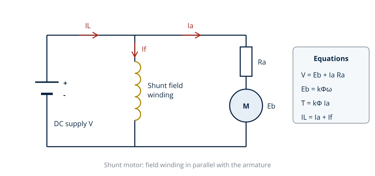
where k is a machine constant set by the number of poles, conductors and parallel paths, ω is speed in rad/s and Ia is armature current. Applying Kirchhoff’s voltage law around the armature circuit gives:
Combining these gives the speed equation:
Speed is therefore proportional to the supply voltage (less the armature voltage drop) and inversely proportional to flux. The power converted from electrical to mechanical form is Eb × Ia, which equals T × ω.
Types of DC motor
DC motors are classified by how the field is supplied.
- Separately excited: the field has its own supply, so field and armature can be controlled independently. This is the classic arrangement for adjustable speed drives.
- Shunt: the field winding is connected in parallel with the armature. With constant supply voltage the flux is nearly constant, so speed falls only slightly as load increases. Used for machine tools, fans and conveyors.
- Series: the field winding is in series with the armature and carries the full armature current. Flux rises with load, so torque rises roughly with current squared below saturation. This gives very high starting torque, but speed rises sharply at light load. Used for traction, cranes and hoists.
- Compound: has both shunt and series windings. In a cumulative compound motor the fields aid each other, giving high starting torque with a limited no load speed. Differential compounding is rarely used because it can be unstable.
- Permanent magnet (PMDC): magnets replace the field winding. They are compact and efficient and are widely used in small and automotive motors, but flux cannot be adjusted.
Brushless DC motors replace the commutator with electronic switching and are closer in construction to synchronous motors. They are compared with other motion motors in servo vs stepper motor.
Starting a DC motor
At standstill ω = 0, so Eb = 0 and the only thing limiting armature current is Ra, which is small. Connecting a motor directly to full voltage would draw a very large current, causing heavy sparking at the commutator and possible damage. Traditional solutions are three point and four point starters, which insert a resistance in series with the armature and cut it out in steps as the speed and back EMF build up. Modern drives use a controlled rectifier or a DC chopper, similar to a buck converter, to ramp the armature voltage up from zero.
Worked example: DC shunt motor
- Given
- 220 V DC shunt motor, armature resistance Ra = 0.5 Ω. At full load the armature current is 20 A and the speed is 1000 rpm.
- Find
- (a) Back EMF at full load, (b) developed torque at full load, (c) speed when the armature current falls to 10 A, (d) the starting resistance needed to limit starting current to 40 A.
- Assumptions
- Constant field flux (shunt field on a constant supply, armature reaction neglected); brush drop neglected.
- Solution
- (a) Eb = 220 - 20 × 0.5 = 210 V
(b) ω = 2π × 1000 / 60 = 104.72 rad/s; T = Eb Ia / ω = 210 × 20 / 104.72 = 40.1 N·m
(c) Eb2 = 220 - 10 × 0.5 = 215 V; N2 = 1000 × 215 / 210 = 1024 rpm
(d) Direct on line current = 220 / 0.5 = 440 A. Total resistance for 40 A = 220 / 40 = 5.5 Ω, so external resistance = 5.5 - 0.5 = 5.0 Ω - Answer
- Eb = 210 V, T = 40.1 N·m, speed at 10 A about 1024 rpm, starting resistance 5.0 Ω
- Limitations
- Developed torque includes rotational losses, so shaft torque is a little lower. Armature reaction slightly weakens the flux at high current, which changes the speed figures in practice.
The result in part (c) shows the shunt motor’s near constant speed: halving the load current raises the speed by under 3 percent.
Speed control of DC motors
From the speed equation, there are three ways to change speed:
- Armature voltage control: varying V with a controlled rectifier or chopper gives smooth control from zero up to base speed at constant torque capability.
- Field weakening: reducing the field current reduces Φ and raises speed above base speed, at constant power capability.
- Armature resistance control: adding series resistance lowers speed but wastes power, so it is now rare.
Advantages and limitations
| Advantages | Limitations |
|---|---|
| Simple, wide range speed control | Brushes and commutator wear and need maintenance |
| High starting torque (series and compound) | Sparking limits use in hazardous areas |
| Good dynamic response | Higher cost and size than an induction motor of equal rating |
| Runs directly from batteries | Commutation limits maximum speed and current |
Related reading
Frequently asked questions
Why should a DC series motor never be started without load?
In a series motor the field current is the armature current. At light load the current is small, so the flux is weak, and the motor speeds up to produce enough back EMF. With no load the speed can rise to dangerous values that damage the armature and commutator. Series motors are therefore always coupled directly or through gears to their load, never through a belt that could slip off.
What is back EMF in a DC motor?
Back EMF is the voltage generated in the armature conductors as they rotate in the magnetic field. It opposes the supply voltage, as Lenz's law requires. It is proportional to flux and speed, and it limits the armature current in normal running. At standstill there is no back EMF, which is why the starting current is high.
How is the direction of a DC motor reversed?
Reverse either the armature current or the field current, but not both. Reversing both leaves the direction of torque unchanged. For a permanent magnet motor the field cannot be reversed, so the armature supply polarity is swapped.
References
- S. J. Chapman, Electric Machinery Fundamentals, 5th ed., McGraw-Hill, 2012
- A. E. Fitzgerald, C. Kingsley and S. D. Umans, Electric Machinery, 7th ed., McGraw-Hill, 2014
- P. C. Sen, Principles of Electric Machines and Power Electronics, 3rd ed., Wiley, 2013
- IEC 60034-1:2022 Rotating electrical machines, Part 1: Rating and performance
- B. L. Theraja and A. K. Theraja, A Textbook of Electrical Technology, Vol. II: AC and DC Machines, S. Chand
Get one engineering email a week
New articles, worked examples and study notes every week. Free, no spam, unsubscribe any time.