Transformer Working Principle, Construction and EMF Equation
The transformer working principle in brief: a transformer is a static machine that transfers electrical energy from one AC circuit to another by mutual induction. It changes the voltage and current levels while the frequency stays the same.
- It works only on AC, because it needs a changing magnetic flux.
- The voltage ratio follows the turns ratio: V1 / V2 ≈ N1 / N2.
- The RMS EMF per winding is E = 4.44 f N Φm.
What is a transformer?
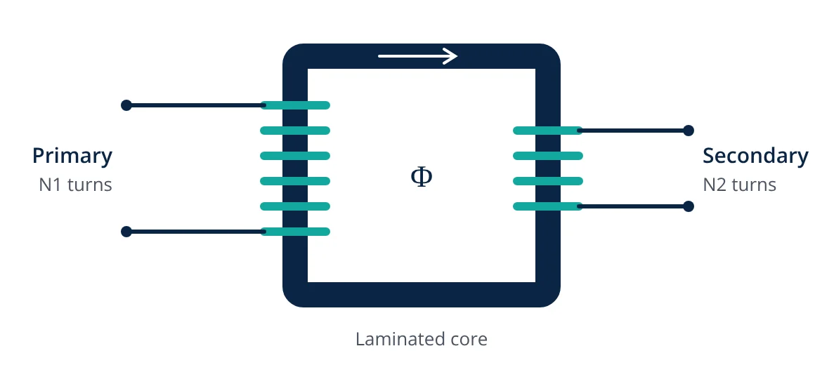
A transformer has two or more windings placed on a common magnetic core. The winding connected to the supply is the primary, and the winding connected to the load is the secondary. There is no electrical connection between the two windings in a two-winding transformer. Energy passes from one to the other only through the magnetic flux in the core.
Because it has no moving parts, a transformer is very efficient. Large power transformers commonly reach efficiencies above 99 percent at their rated load, which is why they can be used at every stage of a power system, from the generator to the distribution network.
Transformer working principle
A transformer works on Faraday’s law of electromagnetic induction: a changing magnetic flux linking a coil induces an EMF in that coil. The operation happens in four steps:
- An alternating voltage V1 is applied to the primary winding, and a small magnetising current flows in it.
- This current sets up an alternating magnetic flux in the core. The core is made of a magnetic material, so almost all the flux stays in it.
- The same alternating flux links the secondary winding and induces an EMF E2 in it. This is mutual induction.
- The flux also links the primary itself and induces a back EMF E1, which opposes the applied voltage and limits the primary current.
When a load is connected to the secondary, a secondary current flows. Its magnetising effect opposes the core flux, so the primary draws extra current to restore the flux. In this way the power drawn by the load is passed from the primary to the secondary through the core.
EMF equation of a transformer
Assume the core flux is sinusoidal, with peak value Φm and supply frequency f:
By Faraday’s law, the EMF induced in a winding of N turns is:
The peak EMF is therefore N ω Φm = 2π f N Φm. For a sinusoid, the RMS value is the peak divided by √2:
Here E is in volts, f in hertz, N is the number of turns and Φm is the peak flux in webers. Applying this to each winding gives E1 = 4.44 f N1 Φm and E2 = 4.44 f N2 Φm.
Turns ratio, voltage ratio and current ratio
Dividing the two EMF equations removes f and Φm, because both windings share the same flux. For an ideal transformer, with no losses and no leakage flux, the induced EMFs equal the terminal voltages and the input power equals the output power. This gives:
- If N2 is greater than N1, the transformer is step-up: the voltage rises and the current falls.
- If N2 is less than N1, the transformer is step-down: the voltage falls and the current rises.
- Given
- Single-phase transformer, primary 230 V, 50 Hz, N1 = 500 turns, required secondary voltage 24 V.
- Find
- Peak core flux Φm and secondary turns N2.
- Assumptions
- Ideal transformer, sinusoidal supply, induced EMF equal to the applied voltage.
- Solution
- Φm = V1 / (4.44 × f × N1) = 230 / (4.44 × 50 × 500) = 230 / 111,000 = 0.00207 Wb
N2 = N1 × V2 / V1 = 500 × 24 / 230 = 52.2, so 52 turns - Answer
- Φm ≈ 2.07 mWb and N2 = 52 turns
- Limitations
- A real transformer has winding resistance and leakage reactance, so the secondary voltage on load is slightly lower than the ideal value. Designers often add a few turns to the secondary to allow for this.
Construction of a transformer
| Part | What it is | Why it matters |
|---|---|---|
| Core | Laminated silicon steel, often cold rolled grain oriented (CRGO) | Carries the flux with low magnetising current; laminations reduce eddy current loss |
| Windings | Copper or aluminium conductors, primary and secondary | The turns ratio sets the voltage ratio |
| Insulation | Paper and mineral oil in oil-filled units; resin or air in dry types | Withstands the voltage between turns, between windings and to earth |
| Tank and conservator | Steel tank holding the oil, with a conservator for oil expansion | Oil-filled units only; the oil also carries heat away |
| Bushings | Insulated terminals bringing the leads through the tank | Rated for the line voltage of each winding |
| Cooling | Radiators, fans or oil pumps | Removes the heat produced by the losses |
There are two basic core arrangements:
- Core type: the windings surround the limbs of the core. This is common for high-voltage power transformers.
- Shell type: the core surrounds the windings, which sit on the central limb. This gives good mechanical support against short-circuit forces.
Losses in a transformer
A real transformer has two main groups of losses:
- Core (iron) losses: hysteresis loss and eddy current loss in the core. They depend on the voltage and frequency and are almost constant at any load.
- Copper losses: I²R loss in the winding resistances. They vary with the square of the load current.
Maximum efficiency occurs at the load where copper loss equals core loss. Both losses are measured by the open-circuit and short-circuit tests. Because distribution transformers are energised all the time but often lightly loaded, low core loss designs, such as those using amorphous metal cores, can save more energy over a year than designs with low copper loss.
Applications
- Power transmission: step-up transformers raise generator voltage so that power can be sent over long lines with lower current and lower I²R loss.
- Distribution: step-down transformers reduce the voltage to levels used by industry and homes, such as 415 V three-phase in many countries.
- Isolation: isolation transformers separate equipment from the supply for safety or noise reduction.
- Electronics: small transformers supply low voltages in power supplies and control circuits.
- Measurement: current and voltage transformers scale large currents and voltages down for meters and protection relays.
Related reading
Frequently asked questions
Why does a transformer not work on DC?
A steady DC current produces a constant flux, so no EMF is induced in the secondary. With no back EMF to limit it, the primary current is set only by the small winding resistance, so the winding can overheat.
Why is the transformer core laminated?
Thin laminations insulated from each other break up the paths of eddy currents in the core. This reduces eddy current loss and the heating it causes.
Does a transformer change the frequency?
No. The secondary voltage has the same frequency as the supply, because both windings are linked by the same alternating flux.
Why are transformers rated in kVA and not kW?
Transformer losses depend on voltage (core loss) and current (copper loss), not on the power factor of the load. The rating is therefore given as apparent power in kVA.
References
- IEC 60076-1:2011, Power transformers, Part 1: General
- S. J. Chapman, Electric Machinery Fundamentals, McGraw-Hill
- A. E. Fitzgerald, C. Kingsley and S. D. Umans, Electric Machinery, McGraw-Hill
Get one engineering email a week
New articles, worked examples and study notes every week. Free, no spam, unsubscribe any time.