Generation, Transmission and Distribution of Electricity
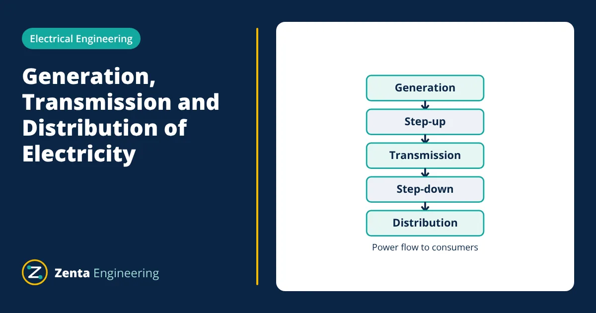
A power system moves electrical energy from where it is generated to where it is used. Generation, transmission and distribution, followed by utilisation, are its four stages:
- Generation at power stations, typically at 11 kV to about 25 kV.
- Transmission over long distances at high voltage, such as 132 kV to 765 kV.
- Sub-transmission and distribution at medium voltage, such as 33 kV and 11 kV.
- Utilisation by consumers at low voltage, such as 400/230 V or 415/240 V.
Transformers in substations change the voltage between stages.
Generation, transmission and distribution: the four stages
Generation
Electricity is generated in thermal, hydro, nuclear, gas and renewable power stations. Large synchronous generators produce three-phase AC at a voltage that is practical for their windings, usually in the range of about 11 kV to 25 kV. Solar and wind plants produce power through inverters or generators and feed it into a collector system before it reaches the grid.
Step-up and transmission
A generator transformer at the power station steps the voltage up to transmission level. Transmission lines then carry bulk power over tens to hundreds of kilometres. Common AC transmission voltages include 132 kV, 220 kV, 400 kV and 765 kV, depending on the country and the distance. Very long links and links between unsynchronised grids may use high voltage direct current (HVDC).
Transmission lines from many power stations are interconnected into a grid. Interconnection lets power flow from where it is generated to where it is needed and keeps supply secure if one station trips.
Sub-transmission and distribution
At grid substations, transformers step the voltage down to sub-transmission levels such as 66 kV or 33 kV. These lines feed distribution substations, which step down again to primary distribution voltages such as 11 kV.
Primary feeders run through towns and industrial areas to distribution transformers, which reduce the voltage to the low voltage used by consumers.
Utilisation
Low voltage supply is three-phase four-wire in most countries. Nominal values listed in IEC 60038 include 230/400 V. Many older systems still use 240/415 V, and North America uses 120/240 V single-phase and 120/208 V or 277/480 V three-phase. Large industrial consumers may take supply directly at 11 kV, 33 kV or higher.
Why high voltage reduces losses
The current in a three-phase line carrying power P at line voltage V and power factor cos φ is:
The power lost as heat in a line with resistance R per phase is:
Because loss depends on the square of the current, and current falls in proportion to voltage, raising the voltage reduces losses with the square of the voltage ratio.
- Given
- 10 MW to be transmitted at power factor 0.9 over a three-phase line with resistance 5 Ω per phase.
- Find
- Line current and line loss at 33 kV and at 132 kV.
- Assumptions
- Balanced load; line reactance and charging current ignored; voltage taken as constant along the line.
- Solution
- At 33 kV: I = 10,000,000 / (1.732 × 33,000 × 0.9) = 194.4 A; loss = 3 × 194.4² × 5 = 567 kW
At 132 kV: I = 10,000,000 / (1.732 × 132,000 × 0.9) = 48.6 A; loss = 3 × 48.6² × 5 = 35.4 kW - Answer
- Loss falls from about 567 kW (5.7 percent) to about 35 kW (0.35 percent), a factor of 16 = (132 / 33)²
- Limitations
- Real lines also have reactance, which causes voltage drop and reactive power flow. Higher voltage needs more insulation, larger towers and costlier equipment, so the voltage chosen is an economic balance.
Substations and their equipment
Substations are where the power system is controlled. A typical substation contains:
| Equipment | Purpose |
|---|---|
| Power transformers | Change voltage between levels |
| Circuit breakers | Switch circuits on load and interrupt fault currents |
| Isolators (disconnectors) | Provide a visible break for safe maintenance, operated off load |
| Busbars | Collect and distribute power between incoming and outgoing circuits |
| Current and voltage transformers | Scale down current and voltage for meters and protection relays |
| Protection relays | Detect faults and trip the correct circuit breakers |
| Lightning arresters | Protect equipment from overvoltage surges |
| Capacitor banks and reactors | Control reactive power and voltage |
Distribution network arrangements
| Arrangement | How it works | Reliability | Typical use |
|---|---|---|---|
| Radial | One feeder supplies loads from one end | A fault cuts off everything beyond it | Rural and low-density areas |
| Ring main | Feeder forms a loop fed from both ends | A faulty section can be isolated and supply restored from the other side | Urban networks, industrial estates |
| Interconnected (mesh) | Several sources feed a meshed network | Highest; loads stay supplied through multiple paths | City centres, critical loads |
Control of the power system
Generation must match demand at every moment. When demand rises faster than generation, the system frequency falls; when generation exceeds demand, it rises. Grid operators keep frequency close to the nominal 50 Hz or 60 Hz by adjusting generator output, and keep voltages within limits using transformer tap changers and reactive power control. SCADA systems collect measurements from substations and let operators switch circuits remotely.
Overhead lines and underground cables
Transmission and distribution circuits use either overhead lines or underground cables:
- Overhead lines use bare conductors, usually aluminium with a steel core, supported on towers or poles by insulators. Air provides the insulation, so they are much cheaper per kilometre and faults are easy to locate and repair.
- Underground cables have solid insulation such as XLPE and are buried or laid in ducts. They cost several times more but are protected from weather and are used in cities, at substations and where overhead routes are not allowed.
AC and HVDC transmission
Most transmission uses three-phase AC, because transformers make it easy to change voltage. High voltage direct current (HVDC) is used in some cases:
| Feature | HVAC | HVDC |
|---|---|---|
| Voltage conversion | Simple, with transformers | Needs converter stations at each end |
| Long overhead lines | Reactive power and stability limit distance | Efficient over very long distances |
| Undersea and underground cables | Cable charging current limits length | Suitable for long cable routes |
| Linking grids at different frequencies | Not possible directly | Possible |
| Terminal cost | Low | High |
For long distances, the lower line cost and losses of HVDC outweigh its expensive converter stations. HVDC is therefore common for long overhead links, subsea cables to offshore wind farms and interconnectors between countries.
Applications of this knowledge
- Plant engineers use it to choose the supply voltage for a new facility and size the incoming transformer.
- Protection engineers use it to coordinate relays from the consumer up to the grid substation.
- Renewable developers use it to decide the voltage level at which a solar or wind farm connects to the grid.
Related reading
Frequently asked questions
Why is electricity transmitted at high voltage?
For the same power, a higher voltage needs a lower current. Line losses are proportional to the square of the current, so raising the voltage four times cuts the losses to about one sixteenth for the same conductor.
What is the difference between transmission and distribution?
Transmission carries bulk power at high voltage over long distances between power stations and major substations. Distribution delivers power at medium and low voltage from local substations to individual consumers.
What is a substation?
A substation is a node in the power system where voltage is changed by transformers, circuits are switched by circuit breakers and isolators, and the network is protected and measured.
References
- J. J. Grainger and W. D. Stevenson, Power System Analysis, McGraw-Hill
- J. D. Glover, M. S. Sarma and T. J. Overbye, Power System Analysis and Design, Cengage
- IEC 60038, IEC standard voltages
Get one engineering email a week
New articles, worked examples and study notes every week. Free, no spam, unsubscribe any time.
