Ship Resistance and Powering Basics
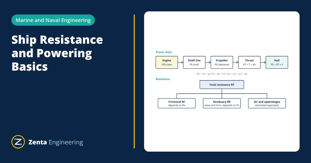
Ship resistance is the force the water and air exert against a ship moving at constant speed. It is made up mainly of frictional resistance, from water shearing along the wetted hull, and residuary resistance, which includes wave making and viscous pressure losses. Resistance times speed gives the effective power. Dividing effective power by the propulsive and shaft efficiencies gives the power the engine must deliver.
Predicting resistance is one of the first tasks in ship design. It sets the size of the main engine, the fuel the ship will burn and its emissions. The methods below follow Molland, Turnock and Hudson, Ship Resistance and Propulsion, and the Principles of Naval Architecture published by SNAME.
Components of ship resistance
A ship moving in calm water experiences several kinds of resistance:
- Frictional resistance (RF): the water in the thin boundary layer next to the hull is dragged along, and the shear stress over the whole wetted surface adds up to a force. For large, slow ships it is the largest component.
- Wave making resistance (RW): the hull creates a wave system at the bow and stern. The energy carried away by these waves must be supplied by the ship. It rises steeply at higher speeds.
- Viscous pressure (form) resistance: the boundary layer thickens towards the stern and may separate, so the pressure on the afterbody does not recover fully. Full, bluff sterns have more of it.
- Appendage resistance: rudders, bilge keels, shaft brackets and stabiliser fins add their own drag.
- Air resistance: the superstructure and deck cargo moving through air, small in still air but larger in a head wind.
- Added resistance in waves: in a seaway the ship needs extra power, which is normally covered by a sea margin.
William Froude grouped wave making and viscous pressure resistance together as residuary resistance (RR), so that total resistance is RT = RF + RR in the simplest form.
Reynolds number, Froude number and model testing
Two dimensionless numbers govern ship resistance. The Reynolds number controls friction and the Froude number controls wave making:
where V is ship speed, L is waterline length, ν is the kinematic viscosity of water and g is gravitational acceleration. Wave patterns of a model and a ship are similar when Froude numbers are equal. Matching Froude number at model scale gives a Reynolds number far smaller than the ship’s, so friction cannot be scaled directly. This is why Froude split the resistance: the model is towed at the correct Froude number, its frictional part is estimated from a flat plate formula and subtracted, and the residuary coefficient is assumed to be the same for model and ship.
Resistance coefficients and the ITTC 1957 line
Resistance is expressed as a non dimensional coefficient based on the wetted surface area S:
The frictional coefficient is normally taken from the ITTC 1957 model ship correlation line, which is used in the ITTC resistance test procedure:
The total coefficient for the ship is then built up as CT = CF + CR + CA, where CR is the residuary coefficient from model tests or a systematic series and CA is a correlation allowance that accounts for hull roughness and other full scale effects. Many tanks also use a form factor (1 + k) multiplying CF, which is the three dimensional method described by Molland and in the ITTC procedures.
Powering: from resistance to engine power
The power needed to tow the hull at speed V is the effective power:
The propeller does not deliver this power perfectly. The propulsion chain has several efficiencies:
- Hull efficiency ηH = (1 - t)/(1 - w): combines the thrust deduction fraction t (the propeller increases the resistance of the hull) and the wake fraction w (the propeller works in water slowed by the hull).
- Open water efficiency ηO: efficiency of the propeller tested alone in uniform flow.
- Relative rotative efficiency ηR: corrects for the non uniform wake behind the hull.
- Shaft efficiency ηS: bearing and stern tube losses between the engine and propeller.
The quasi propulsive coefficient is ηD = ηH ηO ηR, so delivered power PD = PE / ηD, and brake power PB = PD / ηS when there is no gearbox.
Worked example: ship resistance and power
- Given
- Cargo ship, waterline length L = 100 m, wetted surface S = 2500 m², speed 15 knots. Residuary coefficient from model tests CR = 0.0006, correlation allowance CA = 0.0004. Seawater ρ = 1025 kg/m³, ν = 1.1883 × 10⁻⁶ m²/s (ITTC value at 15 °C). Quasi propulsive coefficient ηD = 0.70, shaft efficiency ηS = 0.98.
- Find
- Froude number, Reynolds number, total ship resistance, effective power, delivered power and brake power.
- Assumptions
- Calm deep water; air and appendage resistance included in CA for simplicity; direct drive with no gearbox; 1 knot = 0.5144 m/s; g = 9.81 m/s². The coefficient values are illustrative inputs, not data for a real ship.
- Solution
- V = 15 × 0.5144 = 7.716 m/s
Fn = 7.716 / √(9.81 × 100) = 0.246
Re = 7.716 × 100 / (1.1883 × 10⁻⁶) = 6.49 × 10⁸
CF = 0.075 / (log10(6.49 × 10⁸) - 2)² = 0.075 / (8.812 - 2)² = 0.001616
CT = 0.001616 + 0.0006 + 0.0004 = 0.002616
RT = 0.5 × 1025 × 2500 × 7.716² × 0.002616 = 199.6 kN
PE = 199.6 × 7.716 = 1540 kW
PD = 1540 / 0.70 = 2200 kW
PB = 2200 / 0.98 = 2245 kW - Answer
- Total resistance about 200 kN, effective power about 1.54 MW, brake power about 2.24 MW at 15 knots in calm water
- Limitations
- A real engine rating adds a sea margin for weather and fouling and an engine margin. CR changes strongly with speed and hull form, so it must come from model tests or a recognised systematic series.
In this example friction gives 0.001616 of the 0.002616 total, about 62 percent of the resistance. This shows why hull roughness and fouling matter so much for ships at moderate Froude numbers.
How ship resistance changes with speed
At low Froude numbers, frictional resistance dominates and total resistance rises roughly with the square of speed. As speed increases, the bow and stern wave systems grow and interfere. Wave making resistance rises much faster than speed squared, with humps and hollows depending on whether the bow and stern waves reinforce or cancel. Since power is resistance times speed, power rises faster still. This is why slow steaming, reducing service speed by a few knots, is so effective at cutting fuel use.
Ways to reduce ship resistance
- Hull form: a slender hull with a suitable block coefficient and a well designed bulbous bow reduces wave making at the design speed.
- Smooth hull surface: good coatings and regular cleaning keep frictional resistance close to the design value.
- Stern design: a fair afterbody avoids flow separation and improves the wake for the propeller.
- Trim optimisation: small changes in trim at a given draught can change wave making.
- Appendages: aligning rudders, brackets and fins with the local flow cuts their drag.
Hull form choices also affect ship stability, so the naval architect balances resistance against stability, cargo capacity and seakeeping.
Related reading
Frequently asked questions
Why is ship resistance split into frictional and residuary parts?
Frictional resistance depends mainly on Reynolds number, while wave making resistance depends mainly on Froude number. A scale model cannot match both numbers at once, so Froude's method tests the model at the correct Froude number, removes an estimated frictional part, and scales the remaining residuary part to the full size ship.
What is the difference between effective power and brake power?
Effective power is the power needed to tow the bare hull at a given speed, equal to total resistance times speed. Brake power is the power the main engine must deliver at its output flange. It is larger because of losses in the propeller, the interaction between hull and propeller, and the shaft line.
How does hull fouling affect ship resistance?
Marine growth and paint breakdown increase hull roughness, which raises frictional resistance. Since friction is the largest part of resistance for most slow and medium speed ships, fouling can noticeably increase fuel consumption, which is why hulls are cleaned and recoated at regular dry dockings.
References
- A. F. Molland, S. R. Turnock and D. A. Hudson, Ship Resistance and Propulsion, 2nd ed., Cambridge University Press, 2017
- E. V. Lewis (ed.), Principles of Naval Architecture, Vol. II: Resistance, Propulsion and Vibration, SNAME, 1988
- ITTC Recommended Procedures and Guidelines 7.5-02-02-01, Resistance Test, International Towing Tank Conference
- ITTC Recommended Procedures and Guidelines 7.5-02-01-03, Fresh Water and Seawater Properties, International Towing Tank Conference
- J. Carlton, Marine Propellers and Propulsion, 4th ed., Butterworth-Heinemann, 2018
- K. J. Rawson and E. C. Tupper, Basic Ship Theory, Vol. 2, 5th ed., Butterworth-Heinemann, 2001
Get one engineering email a week
New articles, worked examples and study notes every week. Free, no spam, unsubscribe any time.

