Drag Force on Aircraft: Types and Equation
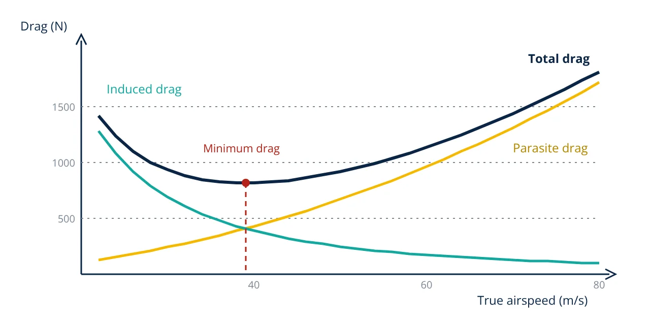
Drag force is the aerodynamic force that opposes an aircraft’s motion, acting parallel to the relative wind. It is found from D = ½ρv²SC_D. Total drag is parasite drag, which grows with the square of speed, plus induced drag, the cost of producing lift, which falls as speed rises. Near and above the speed of sound, wave drag is added.
Drag is one of the four forces of flight. In steady level flight, engine thrust equals drag and lift equals weight. Every reduction in drag means less thrust, less fuel and longer range, so drag prediction and reduction run through every stage of aircraft design.
The drag force equation
The drag equation used throughout aerodynamics, as given by Anderson and by NASA Glenn Research Center, is:
- ρ air density (1.225 kg/m³ at sea level in the standard atmosphere).
- v true airspeed.
- S reference area, normally the wing planform area.
- C_D drag coefficient, which depends on shape, angle of attack (through lift), Reynolds number and Mach number.
The product ½ρv² is the dynamic pressure q, the same term that appears in the lift equation explained in how wings generate lift. Drag and lift are simply the two components of the total aerodynamic force, measured parallel and perpendicular to the relative wind.
Types of drag force on aircraft
Parasite drag
Parasite drag is all drag not associated with producing lift. The FAA Pilot’s Handbook of Aeronautical Knowledge divides it into three kinds:
- Form (pressure) drag: caused by flow separation and the pressure difference between front and rear of a body. Streamlining keeps the flow attached and reduces it.
- Skin friction drag: shear stress in the thin boundary layer on every wetted surface. It depends on wetted area, surface roughness and whether the boundary layer is laminar or turbulent.
- Interference drag: extra drag where components meet, such as the wing to fuselage junction or a strut to wing joint. Fairings and fillets reduce it.
Parasite drag is expressed through the zero lift drag coefficient C_D,0, which is roughly constant at a given Mach number, so parasite drag grows with v².
Induced drag
A finite wing produces lift by creating higher pressure below than above. At the tips, air flows around from the high pressure side to the low pressure side, forming wingtip vortices. These vortices create a downward flow (downwash) over the wing that tilts the local lift vector backward. The rearward component is induced drag. Anderson gives its coefficient as:
where AR = b²/S is the aspect ratio (span squared over wing area) and e is the span or Oswald efficiency factor. Long, slender wings with high aspect ratio produce less induced drag, which is why gliders and long range airliners have them.
Wave drag
As an aircraft approaches the speed of sound, local flow over the wing becomes supersonic and shock waves form. Shocks cause a large pressure rise and can separate the boundary layer, adding wave drag. The Mach number at which drag starts to rise sharply is the drag divergence Mach number. Swept wings, thin airfoils and supercritical airfoil sections delay it, which is why jet airliners use swept wings.
The drag polar and total drag
Combining parasite and induced drag gives the drag polar, the relation between C_D and C_L for the whole aircraft:
Because parasite drag rises with speed and induced drag falls, total drag has a minimum. Anderson shows that minimum drag, and so maximum lift to drag ratio, occurs where the two are equal, C_D,0 = C_D,i, and that:
Flying at the minimum drag speed gives the best glide ratio, and for propeller driven aircraft Anderson shows that maximum range is obtained at maximum L/D. Minimum power required occurs at a lower speed, where induced drag is three times parasite drag.
Worked example: drag force on a light aircraft
- Given
- Light aircraft, mass 1100 kg, wing area S = 16.2 m², aspect ratio AR = 7.5, Oswald factor e = 0.8, zero lift drag coefficient C_D,0 = 0.027. Level flight at sea level, ρ = 1.225 kg/m³, at v = 55 m/s.
- Find
- Lift coefficient, drag coefficient, drag force, power required, and the minimum drag speed and maximum L/D.
- Assumptions
- Lift equals weight; parabolic drag polar; g = 9.81 m/s²; no compressibility effects.
- Solution
- W = 1100 × 9.81 = 10 791 N
q = 0.5 × 1.225 × 55² = 1852.8 Pa
C_L = 10 791 ÷ (1852.8 × 16.2) = 0.360
C_D,i = 0.360² ÷ (π × 0.8 × 7.5) = 0.1293 ÷ 18.85 = 0.00686
C_D = 0.027 + 0.00686 = 0.0339
D = 1852.8 × 16.2 × 0.0339 = 1016 N (parasite 810 N, induced 206 N)
Power required = D × v = 1016 × 55 = 55.9 kW
(L/D)max = 0.5 × √(18.85 ÷ 0.027) = 0.5 × 26.42 = 13.2
At minimum drag, C_L = √(C_D,0 × π e AR) = √(0.027 × 18.85) = 0.713
v_md = √(2 × 10 791 ÷ (1.225 × 16.2 × 0.713)) = 39.0 m/s; D_min = 10 791 ÷ 13.2 = 817 N - Answer
- At 55 m/s the drag force is about 1020 N (L/D about 10.6) and the power required is about 56 kW; minimum drag of about 820 N occurs near 39 m/s with L/D of about 13
- Limitations
- Real drag polars are not exactly parabolic, C_D,0 changes with Reynolds number, flap and gear settings, and propeller efficiency must be included to find engine power.
At cruise, parasite drag is about four fifths of the total, so cleaning up the airframe pays off most. At low speed, as in climb or approach, induced drag dominates.
Key formulas for drag force
| Quantity | Formula | Symbols and units |
|---|---|---|
| Drag force | D = ½ρv²SC_D | ρ air density (kg/m³), v true airspeed (m/s), S wing area (m²), D in N |
| Dynamic pressure | q = ½ρv² | Pa |
| Induced drag coefficient | C_D,i = C_L² ÷ (πe AR) | e = Oswald efficiency factor, AR = aspect ratio |
| Aspect ratio | AR = b² ÷ S | b = wing span (m) |
| Drag polar | C_D = C_D,0 + C_L² ÷ (πe AR) | C_D,0 = zero lift drag coefficient |
| Maximum lift to drag ratio | (L/D)max = ½√(πe AR ÷ C_D,0) | At the minimum drag speed, where C_D,0 = C_D,i |
| Power required | P = D × v | W |
Reducing drag force
- Streamlining fuselages, nacelles and landing gear fairings to delay separation.
- Retractable landing gear and flush rivets to cut parasite drag.
- High aspect ratio wings and winglets to reduce induced drag.
- Laminar flow airfoils and smooth, clean surfaces to reduce skin friction.
- Swept and supercritical wings to raise the drag divergence Mach number.
- Fairings at wing roots and strut joints to cut interference drag.
Engine installation drag also matters; the intake and nozzle design of turbofan and turboprop engines is shaped with this in mind. For small rotorcraft, body and arm drag limit forward speed, as discussed in how a quadcopter flies.
Drag force interview and viva questions
- What are the main types of drag on an aircraft? Parasite drag (form, skin friction and interference drag), induced drag from producing lift, and wave drag near and above the speed of sound.
- Why does induced drag fall as speed increases? At higher speed the wing needs a lower lift coefficient to carry the same weight, and induced drag depends on the square of the lift coefficient.
- At what condition is total drag a minimum? Where parasite drag equals induced drag, which also gives the maximum lift to drag ratio and the best glide.
- Why do gliders have long, slender wings? A high aspect ratio reduces the induced drag coefficient, which is inversely proportional to aspect ratio.
- How do swept wings reduce drag on jet airliners? Sweep, together with thin and supercritical airfoils, delays the drag divergence Mach number, so wave drag rises at a higher speed.
Frequently asked questions
Why does induced drag decrease as speed increases?
In level flight the wing must always produce lift equal to weight. At high speed the dynamic pressure is large, so only a small lift coefficient and a small angle of attack are needed, and the wingtip vortices and downwash are weak. At low speed the wing needs a high lift coefficient, which strengthens the vortices. Induced drag is therefore roughly proportional to one over speed squared.
What is the Oswald efficiency factor?
The Oswald efficiency factor e corrects the ideal induced drag of an elliptical lift distribution for a real aircraft. An ideal elliptical wing has e equal to 1. Real aircraft have values below 1 because of non elliptical lift distribution, fuselage interference and the increase of parasite drag with lift, and design textbooks such as Raymer give typical estimation methods.
How do winglets reduce drag?
Winglets reduce the strength of the wingtip vortices by limiting the flow of high pressure air from below the wing around the tip to the low pressure upper surface. This reduces induced drag, which matters most at the high lift coefficients of climb and long range cruise. They add some weight and parasite drag, so their net benefit depends on the aircraft and mission.
References
- J. D. Anderson Jr., Introduction to Flight, 9th ed., McGraw-Hill
- J. D. Anderson Jr., Fundamentals of Aerodynamics, 6th ed., McGraw-Hill
- D. P. Raymer, Aircraft Design: A Conceptual Approach, 6th ed., AIAA Education Series
- S. F. Hoerner, Fluid-Dynamic Drag, published by the author, 1965
- FAA, Pilot's Handbook of Aeronautical Knowledge, FAA-H-8083-25C, Chapter 5 Aerodynamics of Flight
- NASA Glenn Research Center, Beginner's Guide to Aeronautics: The Drag Equation
Get one engineering email a week
New articles, worked examples and study notes every week. Free, no spam, unsubscribe any time.