Transformer Losses and Efficiency Explained
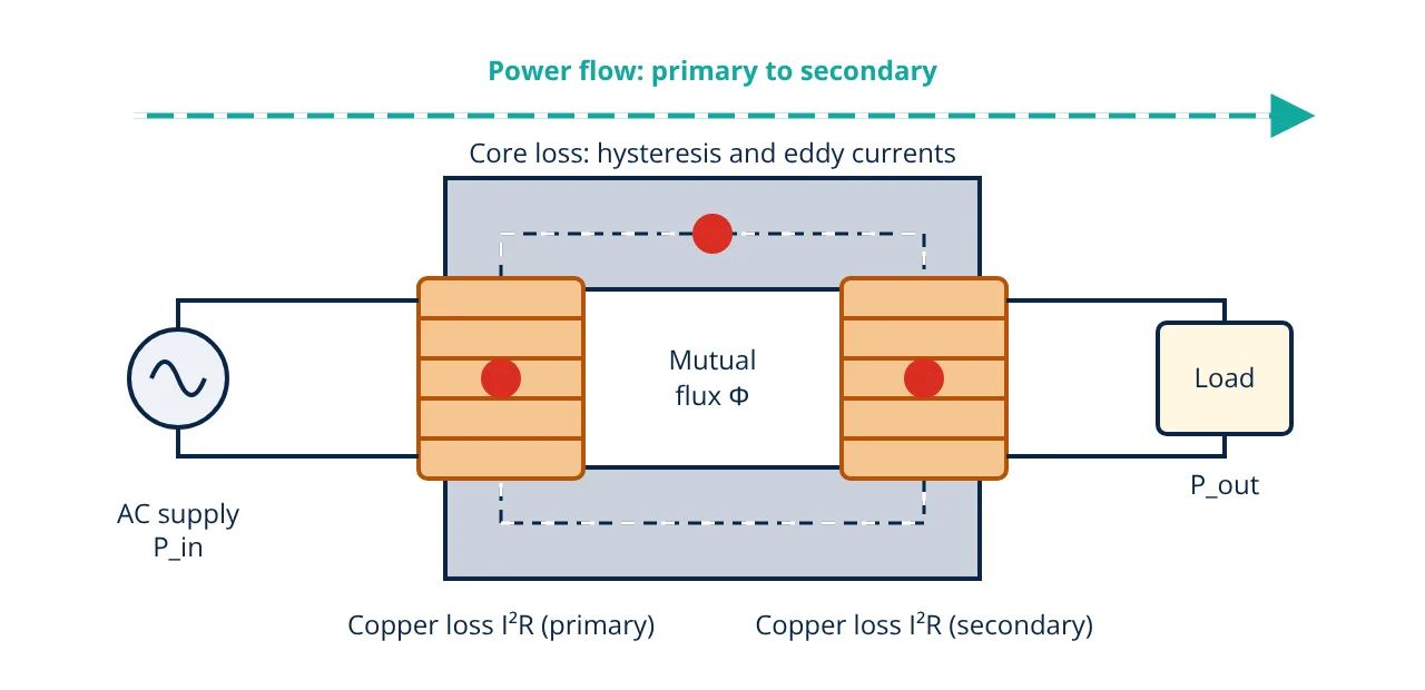
Transformer losses are the power lost as heat inside a transformer while it transfers energy. They are mainly core loss (hysteresis and eddy current loss in the core, almost constant) and copper loss (I²R loss in the windings, varying with load squared). Efficiency is output over input, and it is highest when copper loss equals core loss.
Transformer losses decide how much of the input power actually reaches the load and how hot the transformer runs. A large power transformer may be more than 99% efficient, yet the small percentage lost is still a large amount of energy over a lifetime of continuous service. This article explains where the losses occur, how efficiency is calculated, and why maximum efficiency and all-day efficiency matter when choosing a transformer.
If you are new to the subject, start with the transformer working principle, which explains mutual induction, construction and the EMF equation.
Where transformer losses occur
A transformer has no moving parts, so there is no friction or windage loss. All of its losses occur in two places: the magnetic core and the windings.
Core (iron) loss
Core loss is caused by the alternating flux in the steel core. It has two parts:
- Hysteresis loss: energy used each cycle to reverse the magnetic domains in the steel. It is proportional to frequency and to roughly the 1.6 power of peak flux density (the Steinmetz relation). Grain oriented silicon steel has a narrow hysteresis loop and keeps this loss low.
- Eddy current loss: the changing flux induces circulating currents in the core itself. This loss is proportional to the square of frequency, flux density and lamination thickness, which is why cores are built from thin insulated laminations.
Since flux depends on applied voltage and frequency, and both stay almost fixed in service, core loss is treated as a constant loss that is present whenever the transformer is energised, even at no load.
Copper (winding) loss
Copper loss is the I²R heating in the primary and secondary winding resistances. It depends on load current, so it is a variable loss. At a fraction x of full load, copper loss is x² times the full load copper loss. Half load therefore produces only one quarter of the full load copper loss.
Stray and dielectric losses
Leakage flux induces small eddy currents in the tank, clamps and winding conductors, producing stray load loss. Insulation also has a very small dielectric loss. IEC 60076-1 and IEEE C57.12.00 treat stray loss as part of the measured load loss, so in simple calculations it is included in the copper loss figure.
How transformer losses are measured
Two standard tests give the loss values without loading the transformer with its full output power:
- Open-circuit (no-load) test: rated voltage is applied to one winding with the other open. The wattmeter reads the core loss, because the no-load current is small and its copper loss is negligible.
- Short-circuit (load) test: one winding is shorted and a reduced voltage is applied until rated current flows. Since flux is very low, the wattmeter reads the full load copper loss.
Good insulation resistance readings are normally confirmed before these tests on site.
Efficiency and transformer losses
Efficiency is the ratio of output power to input power. Input equals output plus all losses:
At a load fraction x of the rated apparent power S, with load power factor cos φ:
Here P_i is the core loss and P_cu,fl is the full load copper loss. A lower power factor reduces output for the same current, so efficiency falls even though the losses stay the same. This is also why transformers are rated in kVA rather than kW.
Condition for maximum efficiency
For a fixed power factor, efficiency is highest when the variable loss equals the constant loss:
The kVA at maximum efficiency is x times the rated kVA. Designers choose the ratio of core loss to copper loss so that this peak falls at the load the transformer will see most often.
All-day (energy) efficiency
A distribution transformer stays energised for 24 hours, but its load varies. Its energy efficiency over a day is:
where t_k is the time in hours spent at load fraction x_k. Because the core loss runs all day, low core loss designs often give the best all-day efficiency for lightly loaded distribution transformers.
Worked example: transformer losses and efficiency
- Given
- A 200 kVA single-phase transformer has a core loss of 1.5 kW (open-circuit test) and a full load copper loss of 3.0 kW (short-circuit test). The load power factor is 0.8 lagging.
- Find
- (a) Efficiency at full load. (b) The load in kVA at which efficiency is maximum, and the maximum efficiency.
- Assumptions
- Rated voltage and frequency, so core loss is constant. Stray loss is included in the measured copper loss. Power factor is the same at all loads.
- Solution
- (a) Output = 1 × 200 × 0.8 = 160 kW
Total loss = 1.5 + 3.0 = 4.5 kW
η = 160 ÷ (160 + 4.5) = 0.97264, or 97.26%
(b) x = √(1.5 ÷ 3.0) = 0.7071
Load = 0.7071 × 200 = 141.4 kVA
Output = 141.4 × 0.8 = 113.14 kW
Copper loss = 0.7071² × 3.0 = 1.5 kW, equal to core loss, so total loss = 3.0 kW
η_max = 113.14 ÷ (113.14 + 3.0) = 0.97417, or 97.42% - Answer
- Full load efficiency is about 97.26%. Maximum efficiency is about 97.42% at about 141 kVA (70.7% of rated load).
- Limitations
- Winding resistance rises with temperature, so copper loss should be corrected to the reference temperature given in the standard. Harmonic currents add extra stray loss that this simple model ignores.
Reducing transformer losses
- Core material: cold rolled grain oriented silicon steel or amorphous metal reduces hysteresis loss.
- Thin laminations: thinner insulated sheets cut eddy current loss.
- Larger conductor section: lowers winding resistance and copper loss, at the cost of more copper or aluminium.
- Correct sizing: a transformer far larger than the load keeps a high core loss for little output, while an overloaded one has high copper loss. Sizing practice is similar to cable sizing, where current and heating set the limit.
- Good power factor: correcting power factor lowers current for the same kW and reduces I²R loss in the transformer and the wider power system.
Key formulas for transformer losses
| Quantity | Formula | Symbols and units |
|---|---|---|
| Efficiency | η = P_out ÷ (P_out + P_i + P_cu) × 100% | P_out, P_i, P_cu in kW |
| Copper loss at part load | P_cu = x² × P_cu,fl | x = load fraction of rated kVA, P_cu,fl = full load copper loss in kW |
| Copper loss from current | P_cu = I1² R1 + I2² R2 | I in A, R in Ω |
| Efficiency at load fraction | η = x S cos φ ÷ (x S cos φ + P_i + x² P_cu,fl) | S = rated kVA, cos φ = load power factor |
| Load for maximum efficiency | x = √(P_i ÷ P_cu,fl) | dimensionless; kVA at η_max = x × S |
| All-day efficiency | η_all-day = E_out ÷ (E_out + 24 P_i + Σ x_k² P_cu,fl t_k) | energy in kWh, t_k in h |
Transformer losses interview and viva questions
- What are the main transformer losses? Core loss (hysteresis and eddy current loss in the core) and copper loss (I²R loss in the windings), with small stray and dielectric losses.
- Why are transformer cores laminated? Thin insulated laminations break up the eddy current paths, and eddy current loss falls with the square of lamination thickness.
- What is the condition for maximum efficiency? Efficiency is maximum when copper loss equals core loss, which occurs at a load fraction equal to the square root of core loss divided by full load copper loss.
- Why does efficiency fall at low power factor? The losses depend on voltage and current, not on power factor, so a lower power factor reduces output power for the same losses.
- What is all-day efficiency? It is the ratio of energy output to energy input over 24 hours, and it matters most for distribution transformers that are energised all day at varying load.
Related reading
Frequently asked questions
Why is core loss called a constant loss?
Core loss depends on the applied voltage and frequency, which stay almost fixed in normal service. It is therefore nearly the same from no load to full load, unlike copper loss, which changes with the square of the load current.
Which test measures the core loss and the copper loss of a transformer?
The open-circuit (no-load) test at rated voltage measures the core loss, and the short-circuit test at rated current measures the full load copper loss. Both tests use little energy because the transformer delivers no real output power.
Why are distribution transformers designed for maximum efficiency below full load?
Distribution transformers stay energised all day but are often lightly loaded. Designing them with low core loss places maximum efficiency at a lower load and improves the all-day (energy) efficiency.
References
- IEC 60076-1:2011, Power transformers, Part 1: General
- IEEE Std C57.12.00-2015, IEEE Standard for General Requirements for Liquid-Immersed Distribution, Power, and Regulating Transformers
- S. J. Chapman, Electric Machinery Fundamentals, 5th ed., McGraw-Hill, 2012
- B. L. Theraja and A. K. Theraja, A Textbook of Electrical Technology, Vol. II: AC and DC Machines, S. Chand
- D. P. Kothari and I. J. Nagrath, Electric Machines, 4th ed., McGraw-Hill Education
Get one engineering email a week
New articles, worked examples and study notes every week. Free, no spam, unsubscribe any time.