MCB vs MCCB vs ACB: Differences, Ratings and Uses
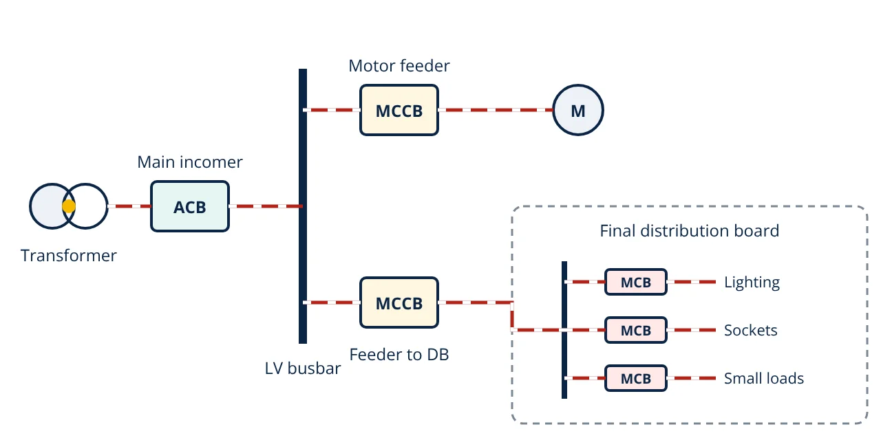
MCB vs MCCB vs ACB: all three are low voltage circuit breakers. An MCB is a fixed trip breaker up to 125 A for final circuits. An MCCB, often adjustable, protects feeders up to about 1600 A. An ACB is a large air breaker with an electronic trip unit for main incomers up to 6300 A.
Comparing MCB vs MCCB vs ACB comes down to current rating, breaking capacity and how much the trip settings can be adjusted. In a typical building, an ACB sits at the main switchboard, MCCBs protect the feeders and MCBs protect the lighting and socket circuits. All three interrupt the arc in air using arc chutes, as described in circuit breaker working principle, but they are built and rated for very different jobs.
MCB vs MCCB vs ACB comparison table
| Feature | MCB | MCCB | ACB |
|---|---|---|---|
| Full name | Miniature circuit breaker | Moulded case circuit breaker | Air circuit breaker |
| Product standard | IEC 60898-1 (household and similar), or IEC 60947-2 | IEC 60947-2 | IEC 60947-2 |
| Rated current | Up to 125 A | From about 16 A up to about 1600 A in common ranges | From about 630 A up to 6300 A |
| Breaking capacity | Rated Icn up to 25 kA | Icu commonly 25 to 100 kA or more | Icu commonly 50 to 150 kA |
| Trip unit | Fixed thermal-magnetic, curve B, C or D | Fixed or adjustable thermal-magnetic, or electronic | Electronic, fully adjustable (long time, short time, instantaneous, earth fault) |
| Short-time withstand Icw | Not rated | Usually not rated (category A) | Rated, so it can delay tripping (category B) |
| Mounting | DIN rail, fixed | Fixed or plug-in, panel mounted | Fixed or draw-out, in a switchboard |
| Operation | Manual toggle | Manual, optional motor operator | Stored energy spring, manual or motor charged, remote close and trip |
| Typical use | Final circuits: lighting, sockets, small loads | Feeders, motor circuits, sub-distribution boards | Main incomers, bus couplers, generator breakers |
The ranges above are typical of manufacturer catalogues. Always check the data sheet of the actual breaker.
Differences between MCB, MCCB and ACB explained
Current rating and frame size
An MCB is a single module, about 18 mm wide per pole, clipped onto a DIN rail. Ratings go up to 125 A. An MCCB is built in a sealed moulded insulating case, and each case size (frame) covers a band of ratings. An ACB is an open frame breaker with large contacts and arc chutes, built for the biggest currents in a low voltage system.
Breaking capacity
IEC 60898-1 gives an MCB a single rated short-circuit capacity Icn, with standard values up to 25 kA. Breakers built to IEC 60947-2 have two ratings:
- Icu, the ultimate breaking capacity: the highest prospective fault current the breaker can interrupt.
- Ics, the service breaking capacity: the fault current it can interrupt and still carry its rated current afterwards. It is given as 25, 50, 75 or 100% of Icu.
The breaking capacity must be at least the prospective short-circuit current where the breaker is installed. Close to a large transformer that current can reach tens of kiloamperes, which is why the incomer is an MCCB or ACB with a high Icu.
Trip units
An MCB has a fixed thermal-magnetic trip. The bimetal handles overload. Under IEC 60898-1 it must not trip at 1.13 × In within one hour, and must trip at 1.45 × In within one hour (for In up to 63 A). The magnetic coil gives instantaneous tripping in a band set by the curve:
| MCB curve | Instantaneous trip band | Typical loads |
|---|---|---|
| B | 3 to 5 × In | Resistive loads, lighting, long cables |
| C | 5 to 10 × In | General commercial loads, small motors |
| D | 10 to 20 × In | Transformers, large motors, high inrush loads |
MCCBs come with fixed or adjustable thermal-magnetic trips, or electronic trip units on larger frames. ACBs almost always use electronic (microprocessor) trip units with long time, short time, instantaneous and earth fault settings, and often metering and communication.
Selectivity and short-time withstand
IEC 60947-2 divides breakers into two utilization categories. Category A breakers have no intentional short-time delay, which covers most MCCBs. Category B breakers have a rated short-time withstand current Icw, so they can stay closed through a downstream fault for a set time. For a breaker rated up to 2500 A, the standard requires Icw of at least 12 × In or 5 kA, whichever is greater, and at least 30 kA above 2500 A. Most ACBs are category B. This is what lets a feeder MCCB clear a fault while the main ACB stays closed. Grading breakers this way is the same idea as coordinating an overcurrent relay.
Mounting, operation and maintenance
MCBs are cheap and sealed, and are replaced rather than repaired. MCCBs are sealed too, though many accept accessories such as shunt trips, auxiliary contacts and motor operators. ACBs are maintainable: draw-out versions slide out of the switchboard to a test or isolated position, and their contacts and arc chutes can be inspected. A stored energy spring mechanism closes them, and they can be closed and tripped remotely.
When to use which breaker
- MCB: final circuits in homes, offices and shops, for lighting, sockets and small appliances, where the fault level at the board is within its Icn.
- MCCB: sub-main feeders, motor circuits such as an induction motor feeder, small incomers and anywhere the current or fault level is beyond an MCB.
- ACB: main incomers from a transformer or generator, bus couplers and large feeders, where high current, high Icu, selectivity and maintainability are needed.
Breakers protect cables, so the breaker rating and the cable rating go together, as covered in cable sizing. The fault current that operates the breaker for an earth fault also depends on the earthing system.
Worked example: choosing breakers for a small building
The full-load current and prospective fault current at the transformer LV terminals are estimated with an infinite source behind the transformer:
- Given
- 630 kVA transformer, 415 V secondary, impedance 5 percent. A lighting circuit on a final distribution board is protected by a 16 A curve B MCB. Prospective fault current at that board is 4.2 kA. Earth fault loop impedance at the far end of the circuit is 0.575 Ω at 230 V.
- Find
- The incomer current and breaking capacity, a suitable MCB breaking capacity, and whether the MCB trips instantaneously for a fault at the far end.
- Assumptions
- Infinite upstream source; bolted fault at the LV terminals; cable impedance to the main switchboard ignored.
- Solution
- IFL = 630,000 / (1.732 × 415) = 876 A
Isc ≈ 876 / 0.05 = 17,530 A, about 17.5 kA
Final circuit fault current = 230 / 0.575 = 400 A
Curve B instantaneous trip needs at most 5 × 16 = 80 A - Answer
- A 1000 A ACB (or large MCCB) incomer with Icu above 17.5 kA; an MCB with Icn of 6 kA (above 4.2 kA); 400 A is above 80 A, so the MCB trips instantaneously
- Limitations
- The transformer estimate ignores source impedance, so it is on the safe side. A full fault study to IEC 60909 includes the network, cables and motor contribution, and selectivity must be checked with the manufacturer’s tables.
Key formulas for MCB vs MCCB vs ACB selection
| Quantity | Formula | Symbols and units |
|---|---|---|
| Transformer full-load current | I_FL = S ÷ (√3 × V) | S in VA, V = line voltage in V, I_FL in A |
| Prospective fault current at LV terminals | I_sc ≈ I_FL ÷ Z_pu | Z_pu = transformer impedance per unit (5% = 0.05) |
| Breaking capacity check | Icu (or Icn) ≥ I_sc | All in kA at the point of installation |
| Service breaking capacity | Ics = k × Icu | k = 0.25, 0.5, 0.75 or 1 |
| Earth fault current at circuit end | I_f = U0 ÷ Zs | U0 = 230 V phase to earth, Zs = loop impedance in Ω |
| MCB instantaneous trip | I_f ≥ m × In | m = 5 (B), 10 (C), 20 (D) |
MCB vs MCCB vs ACB interview and viva questions
- What is the main difference between an MCB and an MCCB? An MCB is a small DIN rail breaker up to 125 A with a fixed trip curve. An MCCB covers higher currents in a moulded case and often has adjustable trip settings and a higher breaking capacity.
- What is the difference between Icu and Ics? Icu is the highest fault current a breaker can interrupt. Ics is the fault current it can interrupt and remain fit for service, stated as a percentage of Icu.
- Why is an ACB rated for Icw? Icw lets the ACB stay closed through a downstream fault for a set time, so the breaker nearest the fault trips first and the rest of the installation keeps supply.
- Which MCB curve suits a transformer or motor load? Curve D, with an instantaneous trip band of 10 to 20 × In, rides through high inrush current.
- How do you choose the breaking capacity of a breaker? It must be at least the prospective short-circuit current at the point of installation, found from a fault calculation.
Related reading
Frequently asked questions
Can an MCCB be used in place of an MCB?
Yes, electrically an MCCB of the right rating can protect a final circuit, but it is larger and costs more. MCBs are made for DIN rail distribution boards in homes and similar installations, so they are the normal choice for small final circuits.
Why are ACBs used as main incomers?
ACBs handle the highest currents in a low voltage switchboard, can carry a fault current for a short time (their Icw rating) so that downstream breakers trip first, have adjustable electronic trip units and are usually draw-out for safe maintenance.
What do Icu and Ics mean on an MCCB?
Icu is the ultimate short-circuit breaking capacity, the highest fault current the breaker can interrupt. Ics is the service breaking capacity, the fault current it can interrupt and still remain fit for normal service. Ics is stated as a percentage of Icu.
References
- IEC 60898-1:2015 Electrical accessories, Circuit-breakers for overcurrent protection for household and similar installations, Part 1: Circuit-breakers for a.c. operation
- IEC 60947-2:2016 Low-voltage switchgear and controlgear, Part 2: Circuit-breakers
- IEC 60364-4-43 Low-voltage electrical installations, Part 4-43: Protection for safety, Protection against overcurrent
- Schneider Electric, Electrical Installation Guide, Chapter H: LV switchgear, functions and selection
- C. H. Flurscheim (ed.), Power Circuit Breaker Theory and Design, IET
Get one engineering email a week
New articles, worked examples and study notes every week. Free, no spam, unsubscribe any time.