Power Transmission Line Losses Explained
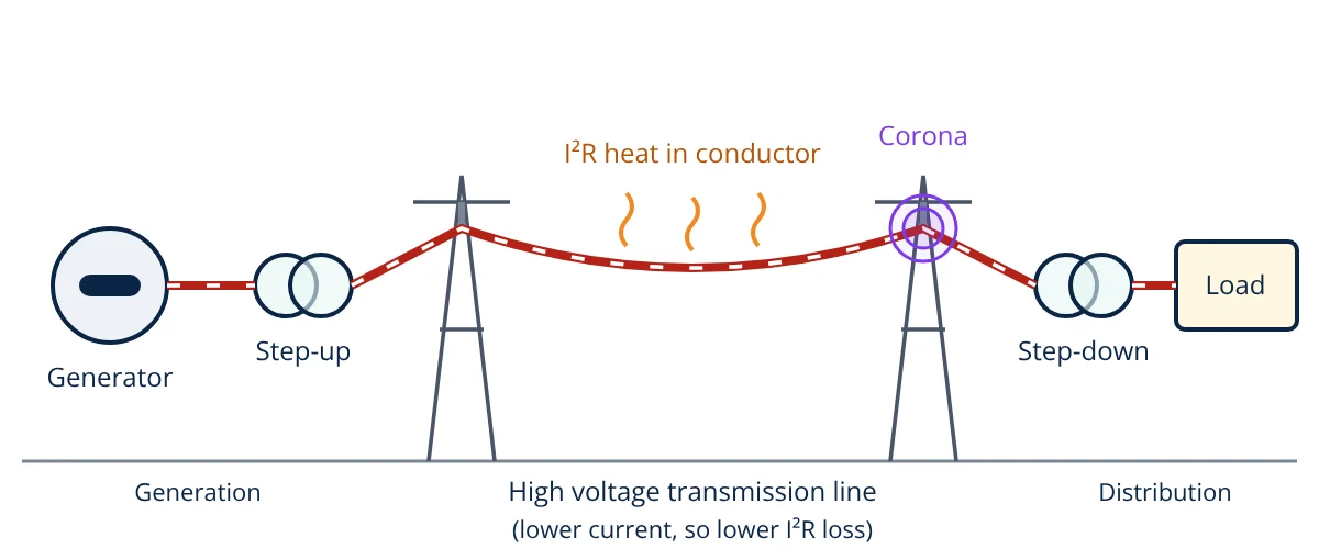
Transmission line losses are the part of the electrical energy sent into a line that is turned into heat and never reaches the load. The largest share is I²R loss in the conductor resistance. Smaller shares come from corona in the air around high voltage conductors, leakage over insulators and, in cables, dielectric loss.
Transmission line losses decide how much of the energy leaving a power station actually arrives at the substation that feeds consumers. Every kilowatt lost is fuel burned or renewable output wasted, so planners, operators and students all need to know where the losses come from, how to calculate them and how to keep them low. This article covers the physics, the formulas, a worked example and the practical ways utilities reduce them.
Where transmission line losses occur
A line is a long conductor with series resistance and inductance, plus shunt capacitance and conductance to earth (Grainger and Stevenson). The losses split into two groups:
- Series (current dependent) losses: heating of the conductor by the load current. They vary with the square of the current, so they change through the day with the load.
- Shunt (voltage dependent) losses: corona discharge in the air, leakage current over insulator surfaces and, for cables, dielectric loss in the insulation. They are present whenever the line is energised, even at no load.
Resistive (I²R) loss
The current that carries power also heats the conductor. For a three-phase line with resistance R per phase, the total resistive loss is three times the loss in one phase (Glover, Overbye and Sarma):
Substituting the current gives a form that shows the design levers directly:
Three points follow:
- Voltage: loss falls with the square of the line voltage for the same power. This is why bulk power moves at high voltage, as explained in generation, transmission and distribution.
- Power factor: loss rises as one over the power factor squared, because reactive current flows in the same conductors.
- Resistance: loss is proportional to R, which depends on conductor material, cross section, length and temperature.
Effect of temperature and skin effect
Conductor resistance increases with temperature. Over the normal operating range it follows R₂ = R₁ [1 + α (T₂ minus T₁)]. IEC 60889 gives α = 0.00403 per °C at 20 °C for hard-drawn aluminium wire. A heavily loaded conductor runs hot, so its resistance and its loss both rise. IEEE Std 738 sets out how to calculate conductor temperature from current, sun, wind and air temperature.
With alternating current, the current crowds towards the outer surface of the conductor. This skin effect makes the AC resistance higher than the DC resistance, and the increase grows with frequency and conductor diameter (Grainger and Stevenson). Manufacturer tables therefore quote AC resistance at a stated temperature, and that value should be used in loss calculations.
Corona loss
At high voltage the electric field at the conductor surface can exceed the breakdown strength of the surrounding air. The air then ionises in a thin layer around the conductor. This is corona, seen as a faint violet glow and heard as a hissing sound, and it also causes radio interference and produces ozone (EPRI Transmission Line Reference Book).
Corona starts above the critical disruptive voltage. Wadhwa gives Peek’s expressions for it and for the fair weather loss:
Here g₀ is about 21.1 kV/cm rms, the breakdown gradient of air at standard conditions. Corona loss grows with the square of the voltage above V_d. It rises sharply in rain, fog and at high altitude, where δ is lower. Rough or dirty conductor surfaces lower the irregularity factor m₀ and so start corona earlier. Larger conductors and bundled conductors reduce the surface gradient and are the standard remedy on extra high voltage lines.
Leakage and dielectric losses
A small current leaks from each conductor to earth over the surface of the insulator strings. It is very small on clean, dry insulators and grows with pollution and moisture. In underground cables the insulation behaves like a lossy capacitor. IEC 60287-1-1 calculates this dielectric loss as W_d = ω C U₀² tan δ per unit length, so it matters mainly at high cable voltages. Cable conductor heating follows the same I²R rule and is covered in cable sizing.
Energy loss over time
Peak power loss is not the same as energy lost over a year, because load varies. Gönen describes the loss factor, the ratio of average loss to loss at peak load. A common empirical approximation links it to the load factor:
Annual energy loss is then peak loss × LLF × 8760 h. Because loss depends on current squared, a peaky load wastes more energy than a flat load carrying the same total energy.
- Given
- A three-phase 132 kV overhead line, 80 km long, delivers 60 MW at power factor 0.9 lagging. Conductor AC resistance is 0.1 Ω/km per phase at 20 °C, aluminium with α = 0.00403 per °C.
- Find
- Line current and I²R loss at 20 °C; loss if the power factor is corrected to 1.0; loss at 0.9 power factor if the conductor runs at 75 °C.
- Assumptions
- Balanced load; voltage taken as 132 kV along the whole line; corona, leakage and charging current neglected.
- Solution
- R = 0.1 × 80 = 8 Ω per phase
I = 60,000,000 ÷ (1.732 × 132,000 × 0.9) = 291.6 A
Loss = 3 × 291.6² × 8 = 2.04 MW (3.40 percent of 60 MW)
At unity power factor: I = 262.4 A; loss = 3 × 262.4² × 8 = 1.65 MW (2.75 percent)
At 75 °C: R = 8 × [1 + 0.00403 × 55] = 9.77 Ω; loss = 3 × 291.6² × 9.77 = 2.49 MW (4.15 percent) - Answer
- About 292 A and 2.04 MW of loss. Unity power factor cuts it to 1.65 MW, while a conductor temperature of 75 °C raises it to 2.49 MW.
- Limitations
- A real line has voltage drop, reactance and charging current, so a full load flow gives more accurate figures. Conductor temperature depends on weather and current, as calculated by IEEE Std 738.
How to reduce transmission line losses
| Method | Why it works |
|---|---|
| Higher transmission voltage | Lower current for the same power; loss falls with voltage squared |
| Reactive power compensation | Capacitors or static compensators near loads cut reactive current in the line |
| Larger or bundled conductors | Lower resistance and lower surface gradient, so less I²R and corona loss |
| Clean, well designed insulators | Less surface leakage in polluted areas |
| Balanced phase loading | Avoids extra current in one phase and in the neutral |
| HVDC for long links | No reactive current or skin effect on the line, though converter stations add their own loss |
Transformers at each end add their own copper and iron losses, which are treated separately in transformer losses and efficiency.
Key formulas for transmission line losses
| Quantity | Formula | Symbols and units |
|---|---|---|
| Line current | I = P ÷ (√3 V_L cos φ) | P in W, V_L line voltage in V, I in A |
| Three-phase I²R loss | P_loss = 3 I² R | R = resistance per phase in Ω |
| Loss in terms of power | P_loss = P² R ÷ (V_L² cos² φ) | Same units as above |
| Resistance at temperature | R₂ = R₁ [1 + α (T₂ minus T₁)] | α = 0.00403 per °C for hard-drawn aluminium at 20 °C |
| Critical disruptive voltage | V_d = m₀ g₀ δ r ln(D ÷ r) | g₀ ≈ 21.1 kV/cm rms, r and D in cm, V_d in kV phase |
| Peek corona loss | P_c = (242 ÷ δ)(f + 25) √(r ÷ D)(V_p minus V_d)² × 10⁻⁵ | kW per km per phase, f in Hz, V_p phase voltage in kV |
| Loss factor | LLF = 0.3 LF + 0.7 LF² | LF = load factor |
The basic relationship between current, voltage and resistance used throughout is Ohm’s law.
Transmission line losses interview and viva questions
- Why are transmission line losses lower at higher voltage? For the same power the current falls in proportion to voltage, and resistive loss depends on current squared, so loss falls with voltage squared.
- Which losses are present on an energised line at no load? Shunt losses: corona, insulator leakage and, for cables, dielectric loss. They depend on voltage, not on load current.
- How do bundled conductors reduce corona loss? Bundling increases the effective radius of each phase, which lowers the electric field at the conductor surface and raises the corona inception voltage.
- Why is AC resistance higher than DC resistance? Skin effect pushes alternating current towards the conductor surface, so the effective conducting area is smaller and the resistance is higher.
- What is loss factor? It is the ratio of average power loss to the loss at peak load over a period. It is used with peak loss to estimate annual energy loss.
Related reading
Frequently asked questions
What is the main cause of transmission line losses?
Resistive heating of the conductors, the I squared R loss, is the largest part on most lines. It rises with the square of the current, so it is highest at peak load. Corona and insulator leakage are smaller and depend mainly on voltage and weather.
Why does a low power factor increase line losses?
For the same real power, a lower power factor needs a larger current, because the line must also carry reactive current. Since resistive loss depends on current squared, the loss rises as one over the power factor squared.
Does corona loss depend on the load current?
No. Corona depends on the voltage gradient at the conductor surface, the conductor radius and spacing, and air conditions such as pressure, temperature, rain and fog. It is present even on a lightly loaded or open ended energised line.
References
- J. J. Grainger and W. D. Stevenson, Power System Analysis, McGraw-Hill, 1994
- J. D. Glover, T. J. Overbye and M. S. Sarma, Power System Analysis and Design, 6th ed., Cengage Learning, 2017
- C. L. Wadhwa, Electrical Power Systems, 7th ed., New Age International, 2017
- T. Gönen, Electric Power Distribution Engineering, 3rd ed., CRC Press, 2014
- EPRI, Transmission Line Reference Book: 345 kV and Above, 2nd ed., Electric Power Research Institute, 1982
- IEEE Std 738-2012, IEEE Standard for Calculating the Current-Temperature Relationship of Bare Overhead Conductors
- IEC 60889:1987 Hard-drawn aluminium wire for overhead line conductors
- IEC 60287-1-1:2023 Electric cables, Calculation of the current rating, Part 1-1: Current rating equations (100 % load factor) and calculation of losses
Get one engineering email a week
New articles, worked examples and study notes every week. Free, no spam, unsubscribe any time.