MPPT Explained: Maximum Power Point Tracking
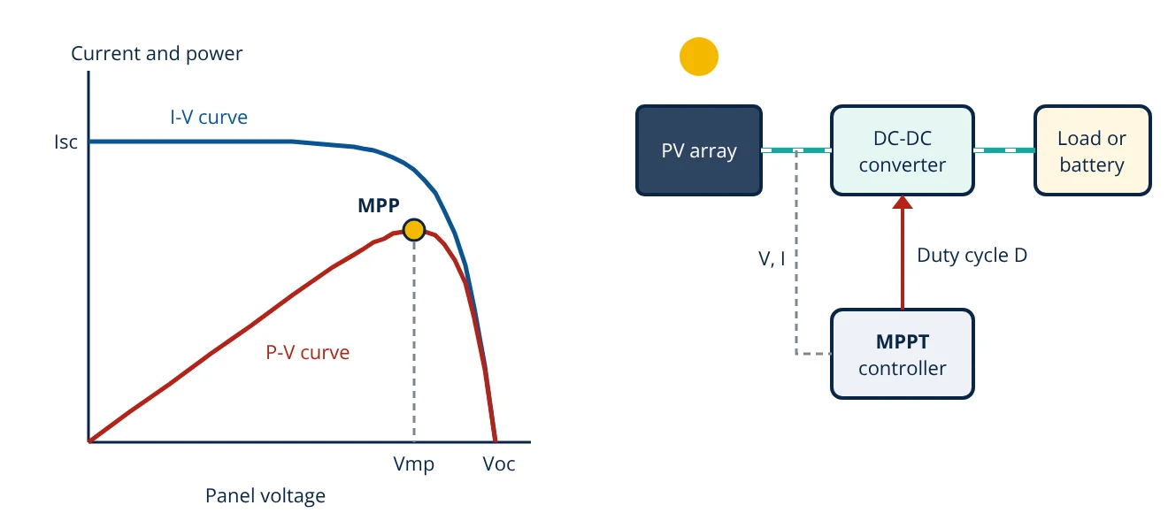
MPPT (maximum power point tracking) is a control method that keeps a solar panel operating at the voltage where its output power is highest. A DC-DC converter or inverter adjusts the panel voltage, measures voltage and current, and keeps moving towards the peak as sunlight and temperature change.
MPPT is built into almost every solar inverter and modern charge controller. A solar panel does not have a fixed output voltage. The voltage and current it delivers depend on the load connected to it, and only one point on its curve gives the most power.
The maximum power point of a solar panel
A solar cell behaves like a current source in parallel with a diode. At zero voltage (short circuit) it delivers its short circuit current Isc. As the voltage rises, the diode starts to conduct and the current falls, slowly at first and then steeply, until it reaches zero at the open circuit voltage Voc. This is the I-V curve.
Power is the product of voltage and current, so the P-V curve is zero at both ends and has a single peak near the knee of the I-V curve. That peak is the maximum power point (MPP), at voltage Vmp and current Imp.
The MPP moves all the time:
- Irradiance mainly changes the current. Halving the sunlight roughly halves Isc and Imp, while Vmp changes only a little.
- Temperature mainly changes the voltage. A hotter cell has a lower Voc and Vmp, so the MPP shifts to the left.
- Partial shading with bypass diodes can give the P-V curve several peaks, only one of which is the true global maximum.
If the panel were connected straight to a load, the operating point would be wherever the load line crosses the I-V curve. A battery, for example, holds the panel close to battery voltage. That point is rarely the MPP, so power is lost. MPPT puts a controllable converter between the panel and the load so the panel can work at Vmp whatever the load needs.
How MPPT moves the operating point
The converter changes the resistance the panel sees. For an ideal buck converter in continuous conduction, the output voltage is D times the input voltage, and the input resistance seen by the panel is:
For an ideal boost converter it is the load resistance multiplied by (1 − D) squared. By changing the duty cycle D, the controller slides the operating point along the I-V curve. The converter types themselves are explained in the buck converter and boost converter articles. In a grid-tied inverter, a DC-DC stage or the inverter’s own DC link voltage control does the same job.
MPPT algorithms
Esram and Chapman compared many tracking techniques. These are the common ones.
Perturb and observe (P&O)
The controller changes the operating voltage by a small step and measures the new power. If power went up, it keeps stepping in the same direction; if power went down, it reverses. This hill climbing method is simple and needs no panel data, which is why it is widely used. Its weaknesses are a steady oscillation around the MPP, set by the step size, and a tendency to step the wrong way when irradiance changes quickly, because the controller cannot tell a change in sunlight from the effect of its own step.
Incremental conductance
At the MPP the slope of the P-V curve is zero. Since P = VI:
The controller compares the incremental conductance dI/dV with the instantaneous conductance minus I/V. If dI/dV is greater than minus I/V, the operating point is left of the MPP and the voltage is raised; if it is smaller, the point is to the right and the voltage is lowered. When they are equal, the tracker holds. This reacts better to fast irradiance changes than basic P&O, at the cost of more computation.
Fractional open circuit voltage and short circuit current
Vmp is roughly proportional to Voc, and Imp is roughly proportional to Isc:
- Vmp ≈ k1 × Voc, with k1 reported between about 0.71 and 0.78.
- Imp ≈ k2 × Isc, with k2 reported between about 0.78 and 0.92.
The controller briefly opens the circuit (or shorts it) to measure Voc (or Isc), then sets the operating point. These methods are cheap but only approximate, and power is lost during each measurement.
Global tracking under shading
When shading creates multiple peaks, P&O and incremental conductance can settle on a local peak. Many inverters add a periodic sweep of the voltage range to find the global peak, then resume local tracking. Module level power electronics (microinverters and power optimisers) avoid much of the problem by giving each module its own tracker.
Where MPPT is used
- String and central inverters, often with two or more independent MPPT inputs for strings with different orientation or length. Inverter types are compared in solar inverter types.
- Microinverters and DC optimisers, which track each module separately.
- MPPT charge controllers in off-grid systems and battery storage.
- Wind turbines and other variable sources, where the same idea is applied to rotor speed.
How well an inverter tracks is measured by its MPPT efficiency, the energy actually drawn from the array divided by the energy theoretically available at the MPP. EN 50530 defines static tests at constant irradiance and dynamic tests with ramps of irradiance.
- Given
- A solar module with Voc = 45 V, Vmp = 34 V, Imp = 9 A and Isc = 9.6 A at the test conditions. It charges a 12 V battery sitting at 13 V. Compare a PWM controller, which connects the module directly to the battery, with an MPPT controller of 96% efficiency.
- Find
- The charging power and battery current in each case.
- Assumptions
- Constant irradiance and temperature. With the PWM controller the module runs at 13 V, on the flat part of its I-V curve, so its current is taken as Isc. Cable and diode losses ignored.
- Solution
- PWM: P = 13 V × 9.6 A = 124.8 W, battery current 9.6 A
Module power at MPP: P = 34 V × 9 A = 306 W
MPPT output: 306 × 0.96 = 293.8 W
Battery current: 293.8 ÷ 13 = 22.6 A
Check fractional Voc: 34 ÷ 45 = 0.76, within 0.71 to 0.78 - Answer
- About 125 W with PWM against about 294 W with MPPT, so MPPT delivers about 2.4 times the charging power in this case
- Limitations
- The gain is largest when panel voltage is far above battery voltage, as here. Real module current at 13 V is slightly below Isc, and panel temperature changes Vmp.
Key formulas for MPPT
| Quantity | Formula | Symbols and units |
|---|---|---|
| Panel power | P = V × I | V in volts, I in amperes, P in watts |
| MPP condition | dP/dV = 0 | Slope of the P-V curve is zero at the peak |
| Incremental conductance test | dI/dV = −I/V at the MPP | Greater than −I/V: left of MPP; smaller: right of MPP |
| Fractional Voc | Vmp ≈ k1 × Voc | k1 about 0.71 to 0.78 |
| Fractional Isc | Imp ≈ k2 × Isc | k2 about 0.78 to 0.92 |
| Buck input resistance | R_in = R_load ÷ D² | D = duty cycle, ideal continuous conduction |
MPPT gets the most out of whatever the panels can produce, but it cannot raise the panels’ own conversion limit, which is discussed in solar panel efficiency. For the complete system around the tracker, see how solar PV systems work.
MPPT interview and viva questions
- What is the maximum power point of a PV module? It is the point on the I-V curve where the product of voltage and current is greatest, at Vmp and Imp, near the knee of the curve.
- Why is a DC-DC converter needed for MPPT? The converter changes the resistance the panel sees through its duty cycle, so the panel can run at Vmp while the load or battery works at its own voltage.
- What is the main drawback of perturb and observe? It oscillates around the MPP in steady state and can step in the wrong direction when irradiance changes quickly.
- State the incremental conductance condition at the MPP. dI/dV equals minus I/V, which comes from setting dP/dV = I + V dI/dV to zero.
- How do irradiance and temperature move the MPP? Higher irradiance raises the current and so the power, while higher temperature lowers the voltage and shifts the MPP to a lower voltage.
Frequently asked questions
Is an MPPT charge controller better than a PWM controller?
An MPPT controller uses a DC-DC converter, so the panel can run at its maximum power point voltage while the battery charges at its own lower voltage. A PWM controller connects the panel almost directly to the battery, which pulls the panel voltage down to battery voltage and wastes the difference. MPPT gains most when the panel voltage is well above the battery voltage.
Why do some inverters have more than one MPPT input?
Each MPPT input tracks the maximum power point of the strings connected to it. Strings facing different directions, with different lengths or with different shading have different maximum power points, so giving them separate trackers stops one string from pulling the other away from its best operating point.
Does MPPT work under partial shading?
Partial shading with bypass diodes creates several peaks on the power-voltage curve. A simple hill climbing tracker can stop on a local peak. Many inverters therefore run a periodic scan of the whole voltage range to find the global peak, then return to normal tracking around it.
References
- T. Esram and P. L. Chapman, Comparison of Photovoltaic Array Maximum Power Point Tracking Techniques, IEEE Transactions on Energy Conversion, vol. 22, no. 2, 2007
- EN 50530:2010, Overall efficiency of grid connected photovoltaic inverters, CENELEC
- A. Luque and S. Hegedus (eds.), Handbook of Photovoltaic Science and Engineering, 2nd ed., Wiley, 2011
- N. Mohan, T. M. Undeland and W. P. Robbins, Power Electronics: Converters, Applications and Design, 3rd ed., Wiley
- IEC 61215, Terrestrial photovoltaic (PV) modules: Design qualification and type approval
Get one engineering email a week
New articles, worked examples and study notes every week. Free, no spam, unsubscribe any time.