Fuel Cell Working Principle and Types
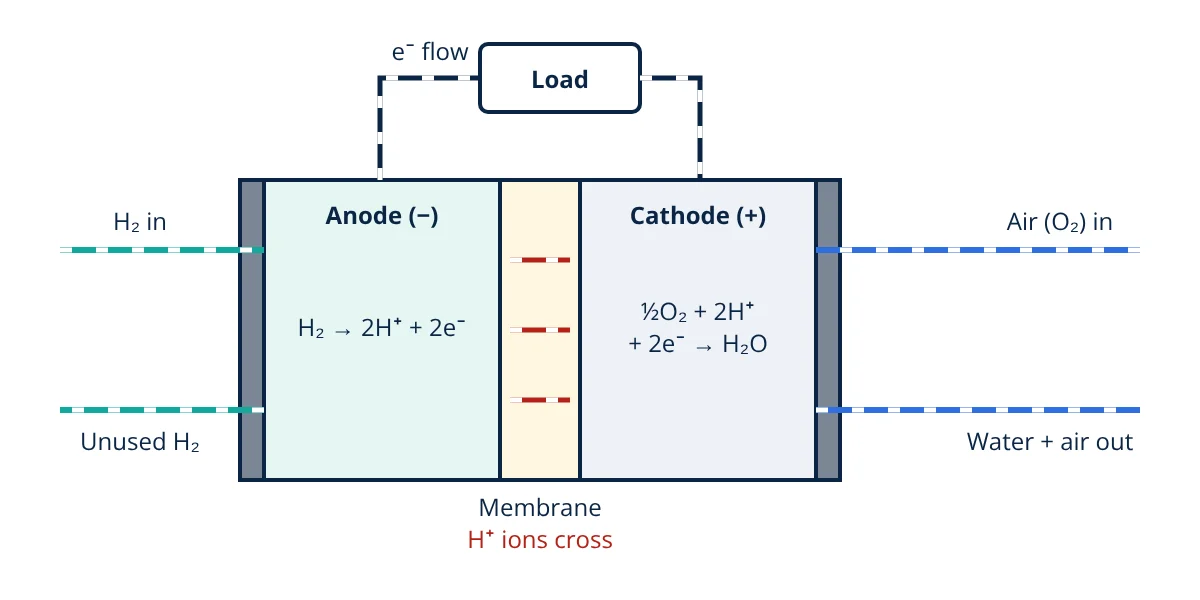
The fuel cell working principle is direct electrochemical conversion: hydrogen is split at the anode into protons and electrons, protons cross an electrolyte, electrons travel through an external circuit as DC current, and both recombine with oxygen at the cathode to form water. No combustion occurs, so efficiency is high and the only product is water and heat.
The fuel cell working principle is the reverse of electrolysis. Instead of using electricity to split water, a fuel cell combines hydrogen and oxygen to produce electricity, water and heat. Because the chemical energy goes straight to electrical energy without burning the fuel, a fuel cell is not limited by the Carnot efficiency of heat engines. Fuel cells now power buses, forklifts, cars, backup systems for telecom sites and stationary combined heat and power units.
Fuel cell working principle step by step
Every fuel cell has three core parts: an anode (fuel electrode), a cathode (air electrode) and an electrolyte between them that conducts ions but not electrons. The proton exchange membrane (PEM) fuel cell is the easiest to follow.
- Fuel supply: hydrogen gas flows through channels in the anode side flow field plate and diffuses through a porous gas diffusion layer to a platinum based catalyst.
- Anode reaction: the catalyst splits each hydrogen molecule into two protons and two electrons.
- Ion transport: the protons pass through the polymer membrane, which is a proton conductor when kept humid.
- Electron flow: the membrane blocks electrons, so they leave the anode through the external circuit, doing useful work in a load such as a motor or inverter.
- Cathode reaction: oxygen from air takes up the arriving protons and electrons and forms water.
- Product removal: water and heat are carried away by the air stream and the cooling system.
The half reactions in a PEM cell are:
and the overall reaction is H₂ + ½O₂ → H₂O. The anode is the negative terminal and the cathode is the positive terminal.
Construction of a fuel cell stack
A single cell is a thin sandwich called the membrane electrode assembly (MEA): the membrane coated on both sides with catalyst layers, covered by gas diffusion layers of carbon paper or cloth. Each MEA sits between two flow field plates (often called bipolar plates) machined or stamped with gas channels. The plates also conduct current to the next cell and carry coolant.
One cell gives well under 1 V, so practical systems connect many cells in series into a stack, in the same way PV modules form strings in solar PV systems. Around the stack, the balance of plant supplies and controls everything else: hydrogen storage and pressure regulation, an air compressor or blower, humidifiers, a cooling loop, sensors, and power electronics such as a DC to DC boost converter or an inverter.
Cell voltage and losses
The maximum electrical work a cell can deliver equals the change in Gibbs free energy of the reaction. For hydrogen and oxygen forming liquid water at 25 °C, Larminie and Dicks give ΔG = −237.2 kJ/mol, so the reversible open circuit voltage is:
where F = 96 485 C/mol is the Faraday constant and 2 is the number of electrons per hydrogen molecule.
Under load, the cell voltage falls because of four losses described by Larminie and Dicks:
- Activation losses: energy needed to drive the electrode reactions, largest at the slow oxygen reduction on the cathode.
- Fuel crossover and internal currents: small amounts of hydrogen and electrons leaking through the electrolyte.
- Ohmic losses: resistance of the membrane, electrodes, plates and contacts, proportional to current.
- Mass transport losses: at high current, reactants cannot reach the catalyst fast enough and voltage drops steeply.
Plotting voltage against current density gives the polarization curve. Most PEM stacks are designed to run near 0.6 to 0.7 V per cell as a compromise between efficiency and power density.
Efficiency and hydrogen consumption
If all the enthalpy of hydrogen (higher heating value, 285.8 kJ/mol) were converted to electricity, the cell voltage would be 1.48 V. Efficiency referred to the higher heating value is therefore simply:
The theoretical limit is 237.2 ÷ 285.8, about 83% (HHV). By Faraday’s law, each cell consumes one mole of hydrogen for every two moles of electrons, so the hydrogen use of a stack of N cells is:
The same relation, run backwards, is used to size electrolysers in green hydrogen electrolysis.
- Given
- A PEM stack of 60 cells operating at 0.7 V per cell and a current of 50 A.
- Find
- Stack voltage, electrical power, hydrogen consumption and HHV efficiency.
- Assumptions
- All cells identical; all hydrogen supplied reacts (no purge losses); F = 96 485 C/mol; H₂ molar mass 2.016 g/mol; HHV 285.8 kJ/mol.
- Solution
- Stack voltage = 60 × 0.7 = 42 V
Power = 42 V × 50 A = 2100 W
Hydrogen = 60 × 50 ÷ (2 × 96 485) = 0.01555 mol/s
Mass flow = 0.01555 × 2.016 = 0.0313 g/s = 112.8 g/h
Efficiency = 0.7 ÷ 1.48 = 0.473 - Answer
- 42 V, 2.1 kW, about 113 g of hydrogen per hour, efficiency about 47% (HHV)
- Limitations
- Real systems purge some hydrogen and spend part of the stack output on the air compressor, pumps and controls, so net system efficiency is lower.
Key formulas for fuel cell working principle
| Quantity | Formula | Symbols and units |
|---|---|---|
| Reversible cell voltage | E₀ = −Δg_f ÷ (2F) | Δg_f = Gibbs free energy change in J/mol, F = 96 485 C/mol; about 1.23 V at 25 °C |
| Stack voltage | V_stack = N × V_c | N = number of cells, V_c = cell voltage in V |
| Stack power | P = N × V_c × I | P in W, I = stack current in A |
| Hydrogen consumption | ṅ = N × I ÷ (2F) | ṅ in mol/s; multiply by 2.016 g/mol for mass flow |
| Efficiency (HHV) | η = V_c ÷ 1.48 | 1.48 V corresponds to the HHV of hydrogen |
Types of fuel cells
Fuel cells are classified by their electrolyte, which sets the operating temperature, the ion that moves and the fuel quality needed. The US DOE comparison of fuel cell technologies lists these main types:
| Type | Electrolyte | Mobile ion | Operating temperature | Typical uses |
|---|---|---|---|---|
| PEMFC | Solid polymer membrane | H⁺ | Below 120 °C | Vehicles, forklifts, backup power |
| AFC | Potassium hydroxide solution | OH⁻ | Below 100 °C | Space, military |
| PAFC | Phosphoric acid in a matrix | H⁺ | 150 to 200 °C | Stationary combined heat and power |
| MCFC | Molten carbonate salts | CO₃²⁻ | 600 to 700 °C | Large stationary plants |
| SOFC | Ceramic such as yttria stabilised zirconia | O²⁻ | 500 to 1000 °C | Stationary power, combined heat and power |
Low temperature cells
PEM and alkaline cells start quickly and suit transport and portable use, but need platinum or other precious metal catalysts and fairly pure hydrogen. Carbon monoxide poisons the platinum in a PEM cell even at low concentrations. The direct methanol fuel cell is a PEM variant fed with methanol for small portable devices.
High temperature cells
Molten carbonate and solid oxide cells run hot enough to reform natural gas or biogas internally, use cheaper nickel catalysts and tolerate carbon monoxide as a fuel. Their waste heat is useful for combined heat and power. The trade off is slow start up and demanding materials.
Advantages and limitations
Advantages:
- High electrical efficiency because there is no combustion step.
- Zero point of use emissions with hydrogen, and quiet operation with few moving parts.
- Modular: power scales with the number of cells and stacks.
- Fast refuelling compared with charging a battery, which is why fuel cells compete with battery energy storage systems in heavy transport and long duration backup.
Limitations:
- Hydrogen production, storage and distribution are costly, and most hydrogen today is still made from fossil fuels.
- Precious metal catalysts and membranes add cost, and catalysts and membranes degrade over time.
- Low temperature cells need water and heat management to keep the membrane humid without flooding the electrodes.
- Safety: hydrogen has a wide flammability range, so modules must meet standards such as IEC 62282-2-100 for leak detection, ventilation and protection.
Applications
- Transport: fuel cell electric cars, buses, trucks, trains and material handling vehicles.
- Stationary power: combined heat and power for buildings, prime power for data centres and backup for telecom towers.
- Grid support: converting stored hydrogen back to electricity in renewable rich microgrids.
- Portable and space: alkaline cells supplied power and drinking water on crewed spacecraft.
Fuel cell working principle interview and viva questions
- What is the basic fuel cell working principle? Fuel is oxidised at the anode and oxidant reduced at the cathode, with ions crossing the electrolyte and electrons flowing through an external circuit, converting chemical energy directly into DC electricity.
- Why is a fuel cell not limited by the Carnot efficiency? It does not convert fuel energy to heat and then to work; the electrochemical reaction delivers electrical work directly, limited only by the Gibbs free energy of the reaction.
- What is the reversible voltage of a hydrogen fuel cell at 25 °C? About 1.23 V, found from E₀ = −Δg_f ÷ 2F with Δg_f = −237.2 kJ/mol for liquid water product.
- Which ion moves in a PEM cell and in a solid oxide cell? Protons (H⁺) move from anode to cathode in a PEM cell, while oxide ions (O²⁻) move from cathode to anode in a solid oxide cell.
- Why must the PEM membrane be kept humid? The polymer conducts protons only when hydrated; a dry membrane raises ohmic resistance and lowers performance, while excess water floods the electrodes.
Frequently asked questions
Is a fuel cell the same as a battery?
Both are electrochemical devices that turn chemical energy into DC electricity. A battery stores its reactants inside and must be recharged or replaced, while a fuel cell is supplied continuously with fuel and oxidant from outside and keeps producing power as long as they flow.
Why does a single fuel cell give less than 1.23 V?
1.23 V is the reversible voltage at 25 °C. Real cells lose voltage to activation losses at the electrodes, ohmic resistance in the membrane and contacts, mass transport limits at high current and fuel crossover, so a cell under load typically runs at about 0.6 to 0.7 V.
What comes out of a hydrogen fuel cell exhaust?
When fed with pure hydrogen and air, the only chemical product is water, together with heat and oxygen depleted air. There is no carbon dioxide at the point of use, although emissions do arise upstream if the hydrogen was made from fossil fuels.
References
- J. Larminie and A. Dicks, Fuel Cell Systems Explained, 2nd ed., Wiley, 2003
- US Department of Energy, Hydrogen and Fuel Cell Technologies Office, Comparison of Fuel Cell Technologies and Fuel Cell Basics
- IEC 62282-2-100:2020 Fuel cell technologies, Part 2-100: Fuel cell modules, Safety
- R. O'Hayre, S. W. Cha, W. Colella and F. B. Prinz, Fuel Cell Fundamentals, 3rd ed., Wiley, 2016
- US DOE, Fuel Cell Technologies Office Multi-Year Research, Development and Demonstration Plan, Section 3.4 Fuel Cells
Get one engineering email a week
New articles, worked examples and study notes every week. Free, no spam, unsubscribe any time.