How Wind Turbines Generate Electricity
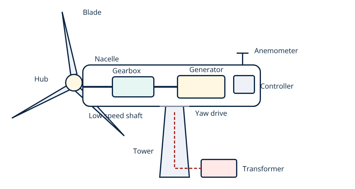
Wind turbines convert the kinetic energy of moving air into electricity. Wind flowing over the aerofoil shaped blades creates lift, which turns the rotor. The rotor drives a generator, often through a gearbox that raises the speed, housed in the nacelle on top of a tall tower. Pitch control adjusts blade angle to limit power in strong winds, and yaw control keeps the rotor facing the wind. Power rises with the cube of wind speed, but no turbine can capture more than 59.3% of the wind’s energy, the Betz limit.
Wind power is one of the largest sources of renewable electricity. Modern turbines are huge: onshore machines commonly have rotors over 150 m in diameter and ratings of 4 to 7 MW, while offshore turbines exceed 14 MW with rotors over 220 m. Yet the working principle is straightforward aerodynamics and electrical engineering.
Power in the wind
The power carried by wind through the area swept by the rotor is:
where ρ is air density (about 1.225 kg/m³ at sea level), A the swept area (πR²) and v the wind speed. Two consequences dominate turbine design:
- Cube of speed: doubling the wind speed gives eight times the power, so sites with higher average winds are far more valuable, and towers are tall to reach stronger winds.
- Area: doubling rotor diameter quadruples the area and the power, which is why rotors keep growing.
A turbine extracts only part of this power:
The power coefficient C_p cannot exceed the Betz limit of 16/27, or 59.3%, because the air must keep moving to leave the rotor. Modern turbines reach C_p of about 0.45 to 0.50 at their best operating point.
How the blades work
Blades are long aerofoils, like aircraft wings. The wind seen by the blade combines the real wind and the blade’s own motion. Air flows faster over the curved suction side, lowering pressure there, and the pressure difference produces lift roughly perpendicular to that relative flow. The component of lift in the direction of rotation produces torque. Blades are twisted along their length because the tip moves much faster than the root; the tip speed ratio, tip speed divided by wind speed, is typically around 7 to 9 for three blade turbines. Blades are made from glass or carbon fibre composites for strength and low weight.
Main components of wind turbines
- Rotor: blades plus hub. The hub contains pitch bearings and pitch drives.
- Main shaft and bearings: carry the rotor loads at low speed, around 5 to 15 rpm on large turbines.
- Gearbox: a multistage planetary and parallel gearbox raises speed to about 1000 to 1800 rpm for a conventional generator.
- Generator: commonly a doubly fed induction generator (DFIG) with a partial power converter, or a permanent magnet synchronous generator with a full power converter. Direct drive turbines omit the gearbox and use a large, slow, multipole generator, reducing maintenance.
- Power converter and transformer: convert variable frequency output to grid frequency and step up voltage to the collection network.
- Yaw system: motors turn the nacelle to face the wind, guided by a wind vane.
- Brakes: aerodynamic braking by pitching blades, plus a mechanical disc brake for parking.
- Controller: monitors wind, speed, temperatures and vibration and controls pitch, yaw and generator torque.
- Tower and foundation: steel tubular or hybrid concrete towers, often over 100 m tall, on concrete foundations onshore or monopiles, jackets or floating platforms offshore.
The power curve
A turbine’s power curve shows electrical output against wind speed:
- Cut-in speed (about 3 m/s): the rotor starts producing power.
- Region 2: output rises roughly with the cube of wind speed; the controller varies rotor speed to keep the tip speed ratio, and C_p, at their best.
- Rated speed (about 11 to 13 m/s): rated power is reached.
- Region 3: pitch control sheds excess energy to hold output at rated power.
- Cut-out speed (about 25 m/s): the turbine stops for protection.
- Given
- A turbine has a rotor diameter of 120 m and C_p = 0.45. Air density is 1.225 kg/m³.
- Find
- Power output at wind speeds of 6 m/s and 9 m/s.
- Assumptions
- Below rated speed; drivetrain and electrical losses ignored.
- Solution
- A = π × 60² = 11 310 m²
At 6 m/s: P = 0.5 × 1.225 × 11 310 × 216 × 0.45 = 673 kW
At 9 m/s: v³ = 729; P = 0.5 × 1.225 × 11 310 × 729 × 0.45 = 2273 kW - Answer
- About 0.67 MW at 6 m/s and 2.27 MW at 9 m/s: a 50% rise in wind speed gives about 3.4 times the power
- Limitations
- C_p varies with wind speed; above rated speed output is capped by pitch control.
Wind resource and siting
Because power depends on the cube of wind speed, careful site assessment is essential. Developers measure wind with met masts or lidar for at least a year, correlate with long term reference data, and model the Weibull distribution of wind speeds. Wind speed rises with height, often following a power law, so taller towers reach stronger, steadier winds. Turbines in a wind farm are spaced several rotor diameters apart, because each turbine leaves a slower, turbulent wake that reduces the output of turbines downwind. Terrain, obstacles, noise limits, bird and bat habitats, grid access and transport routes for blades also shape the layout.
Onshore and offshore wind
Onshore wind is the cheaper and more established option, limited by land use, transport of large blades and local acceptance. Offshore wind benefits from stronger, steadier winds and room for larger turbines, at the cost of complex foundations, subsea cables and marine operations. Floating foundations, similar in concept to offshore platforms, open up deep water sites.
Wind turbines and the grid
Because wind varies, wind farms are combined with other generation, storage such as battery energy storage systems, and forecasting. Modern turbine converters provide grid support functions such as voltage control, fault ride through and fast frequency response. Like solar PV systems, wind farms feed the transmission and distribution network through step up transformers.
Frequently asked questions
Why do wind turbines have three blades?
Three blades give a good balance of efficiency, cost and smooth operation. Two blade rotors are cheaper but suffer uneven loads as the blades pass the tower and when the turbine yaws, and they look visually less smooth. More than three blades adds cost and weight for very little extra energy.
What is capacity factor?
Capacity factor is the actual energy a turbine produces in a year divided by the energy it would produce running at full rated power all year. Onshore wind farms typically achieve about 25 to 40%, and modern offshore farms about 40 to 50%, because winds vary.
Why do turbines stop in very strong winds?
Above the cut-out speed, typically around 25 m/s, loads on the blades, drivetrain and tower could cause damage. The control system pitches the blades to feather and applies the brake, stopping or idling the rotor until the wind drops.
References
- IEC 61400-1, Wind energy generation systems: Design requirements
- IEC 61400-12-1, Power performance measurements of electricity producing wind turbines
- T. Burton, N. Jenkins, D. Sharpe and E. Bossanyi, Wind Energy Handbook, 3rd ed., Wiley
- J. F. Manwell, J. G. McGowan and A. L. Rogers, Wind Energy Explained, 2nd ed., Wiley
Get one engineering email a week
New articles, worked examples and study notes every week. Free, no spam, unsubscribe any time.