Vapour Compression Refrigeration Cycle Explained
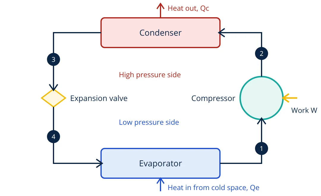
In the vapour compression refrigeration cycle, a refrigerant absorbs heat by evaporating at low pressure in the evaporator, is compressed to high pressure and temperature, rejects heat by condensing in the condenser, then drops back to low pressure through an expansion valve. The cycle repeats continuously. Its performance is measured by the coefficient of performance, COP = cooling effect / compressor work.
Almost every refrigerator, air conditioner, chiller and heat pump uses the vapour compression refrigeration cycle. It moves heat from a cold space to a warmer one, which the second law of thermodynamics says can only happen with a work input. The trick is to make the refrigerant boil at a temperature below the space being cooled and condense at a temperature above the surroundings, by changing its pressure.
Components of the vapour compression refrigeration cycle
The refrigerant passes through four processes:
- Compression (1 to 2): low pressure vapour, slightly superheated, enters the compressor. The compressor raises its pressure and temperature. Ideally this is isentropic (constant entropy).
- Condensation (2 to 3): hot high pressure vapour enters the condenser. It first cools to the saturation temperature, then condenses to liquid, rejecting heat to outdoor air or cooling water. The liquid usually leaves slightly subcooled.
- Expansion (3 to 4): high pressure liquid passes through the expansion device. Pressure falls sharply and part of the liquid flashes to vapour, which cools the mixture to the evaporating temperature. No work is done and heat transfer is negligible, so enthalpy is constant (h₄ = h₃).
- Evaporation (4 to 1): the cold liquid and vapour mixture enters the evaporator, absorbs heat from the space or the fluid being cooled and boils to vapour. This is the useful refrigeration effect.
The condenser must be warmer than the surroundings and the evaporator colder than the space, so heat can flow by the normal modes of heat transfer. Pressure sets each saturation temperature, which is why the system has a high pressure side and a low pressure side.
Analysing the cycle on the p-h diagram
Refrigeration engineers plot the cycle on a pressure enthalpy (p-h) chart. Each process becomes a simple line: two horizontal lines at constant pressure (evaporation and condensation), a vertical line for expansion (constant enthalpy) and a steep line for compression. Applying the steady flow energy equation to each component gives:
per kilogram of refrigerant. The refrigeration effect is qe and the compressor work is w. Energy balance gives qc = qe + w: the condenser rejects the heat absorbed plus the work input.
The coefficient of performance of a refrigerator is:
The upper limit, set by the reversed Carnot cycle, is COP = Te / (Tc minus Te) with absolute temperatures. A smaller temperature lift between evaporator and condenser gives a higher COP, which is why dirty condensers and low evaporator settings waste energy. For a heat pump, the useful output is qc, so COP_HP = COP_R + 1.
- Given
- A simple cycle evaporates at minus 10 °C and condenses at 40 °C. Enthalpies (illustrative, rounded values for a common HFC refrigerant): h₁ = 395 kJ/kg, h₂ = 425 kJ/kg, h₃ = h₄ = 255 kJ/kg. Refrigerant mass flow is 0.1 kg/s.
- Find
- Refrigeration capacity, compressor power, heat rejected, COP and the Carnot COP.
- Assumptions
- Steady flow; no pressure drop in pipes and heat exchangers; kinetic and potential energy changes negligible.
- Solution
- qe = 395 − 255 = 140 kJ/kg; Qe = 0.1 × 140 = 14 kW (14 / 3.517 = 3.98 TR)
w = 425 − 395 = 30 kJ/kg; W = 0.1 × 30 = 3 kW
Qc = 14 + 3 = 17 kW
COP = 14 / 3 = 4.67
Carnot COP = 263.15 / (313.15 − 263.15) = 5.26 - Answer
- About 14 kW (4 TR) of cooling for 3 kW of compressor power, COP 4.7, against a Carnot limit of 5.3
- Limitations
- Use real refrigerant table values for design. Real compressors are not isentropic, so actual shaft power is higher.
Ideal and actual cycles
The simple cycle described above is called the ideal vapour compression cycle. A real system differs from it in several ways that reduce COP:
- Compressor losses: friction and heat transfer make the compression non-isentropic, so the discharge enthalpy and the work input are higher than ideal. Isentropic efficiency is used to correct for this.
- Pressure drops: friction in the condenser, evaporator and connecting pipes means the compressor must work over a larger pressure ratio. The pipe friction is calculated with the same methods used for liquids and the Bernoulli equation extended with losses.
- Heat gains: the suction line picks up heat from the surroundings, raising superheat and the specific volume entering the compressor.
- Temperature differences: the evaporator must run several kelvin below the space temperature, and the condenser several kelvin above the ambient, to drive heat transfer. These differences lower the evaporating pressure and raise the condensing pressure, increasing compressor work.
Good design keeps these losses small: generous heat exchanger surface, short and correctly sized pipes, insulated suction lines and efficient compressors with variable speed drives for part load.
Refrigerants and practical points
- Refrigerants are chosen for suitable pressures, safety class, efficiency and environmental impact. Older CFCs and HCFCs have been phased out under the Montreal Protocol, and high global warming potential HFCs are being phased down. Ammonia, CO₂, hydrocarbons and low GWP HFOs are increasingly used.
- Superheat and subcooling: a few kelvin of superheat protects the compressor from liquid; subcooling increases the refrigeration effect.
- Compressor types: reciprocating, rotary, scroll, screw and centrifugal, chosen by capacity. Large centrifugal chillers work like a centrifugal pump acting on vapour.
- Lubrication: compressor oil must be compatible with the refrigerant and return from the evaporator. See types of lubrication.
- Monitoring: suction and discharge pressure, superheat and approach temperatures reveal most faults. Sensors for these use standard temperature measurement and pressure measurement techniques.
Common faults
- Low refrigerant charge: low suction pressure, high superheat, reduced capacity.
- Dirty condenser or failed fan: high discharge pressure, high power, low COP.
- Blocked expansion device or filter drier: starved evaporator, low suction pressure.
- Non-condensable gases: high condensing pressure that does not match the condensing temperature.
Related reading
Frequently asked questions
What are the four main components of a vapour compression refrigeration system?
The compressor, the condenser, the expansion device (a capillary tube, thermostatic expansion valve or electronic expansion valve) and the evaporator. They are connected in a closed loop through which the refrigerant circulates.
Why is the expansion process treated as constant enthalpy?
The refrigerant passes through a small restriction quickly, with negligible heat transfer and no work. The steady flow energy equation then gives equal enthalpy before and after, even though pressure and temperature drop sharply.
What is one ton of refrigeration?
One ton of refrigeration (TR) is a cooling rate of 12,000 Btu/h, about 3.517 kW. It comes from the heat needed to melt one short ton of ice in 24 hours.
Why does the refrigerant leave the evaporator superheated?
A few kelvin of superheat makes sure only vapour reaches the compressor. Liquid droplets entering a compressor can damage valves and other parts, so expansion valves are set to control superheat.
References
- Y. A. Cengel and M. A. Boles, Thermodynamics: An Engineering Approach, 9th ed., McGraw-Hill, chapter on refrigeration cycles
- W. F. Stoecker and J. W. Jones, Refrigeration and Air Conditioning, 2nd ed., McGraw-Hill
- C. P. Arora, Refrigeration and Air Conditioning, 3rd ed., McGraw-Hill Education
- ASHRAE Handbook, Refrigeration, ASHRAE
Get one engineering email a week
New articles, worked examples and study notes every week. Free, no spam, unsubscribe any time.