Limit State Design of RCC: Basic Concepts
Limit state design checks that a reinforced concrete structure does not reach any condition, called a limit state, that makes it unfit for use. The limit state of collapse is checked with loads increased and material strengths reduced by partial safety factors. The limit states of serviceability check deflection and cracking under normal loads. In India it is the main method of IS 456:2000.
Reinforced cement concrete (RCC) combines concrete, which is strong in compression, with steel bars that carry tension. Designing it means deciding the size of members and the amount and position of steel. Older practice used the working stress method; modern codes, including IS 456 and Eurocode 2, use limit state design because it treats safety and serviceability separately and accounts for uncertainty in a more rational way.
What is a limit state?
A limit state is a condition beyond which a structure, or part of it, no longer meets its design requirements. They fall into two groups.
Limit state of collapse (ultimate limit state) covers safety against failure:
- flexure (bending)
- compression (columns)
- shear and torsion
- bond and anchorage of bars
- overall stability: overturning and sliding
Limit states of serviceability cover performance in normal use:
- deflection, which can crack finishes and partitions or look unsafe
- cracking, which spoils appearance and lets in water that corrodes steel
- vibration, durability and fire resistance, which are handled by detailing rules
The structure must satisfy every relevant limit state. Usually the design is made for collapse and then checked for serviceability.
Characteristic values and partial safety factors
Limit state design uses statistics. The characteristic strength of a material is the value below which not more than 5 percent of test results are expected to fall. For concrete it is fck, the 28 day cube strength (M20 means fck = 20 N/mm²). For steel it is fy, the yield or 0.2 percent proof stress (Fe415 means fy = 415 N/mm²). Characteristic loads are the values specified in the loading codes, such as IS 875.
Partial safety factors then cover the remaining uncertainties:
| Item (IS 456, limit state of collapse) | Partial safety factor |
|---|---|
| Concrete strength, γm | 1.5 |
| Steel strength, γm | 1.15 |
| Dead load + imposed load | 1.5 (DL + IL) |
| Dead + imposed + wind or earthquake | 1.2 (DL + IL + WL or EL) |
| Dead + wind, where DL is favourable | 0.9 DL + 1.5 WL |
Design strength = characteristic strength / γm, and design load = characteristic load × γf. This is the same idea as an overall factor of safety, split between load and material so each uncertainty gets its own factor.
Assumptions for flexure in IS 456
At the limit state of collapse in bending, IS 456 assumes:
- Plane sections remain plane, so strain varies linearly with depth.
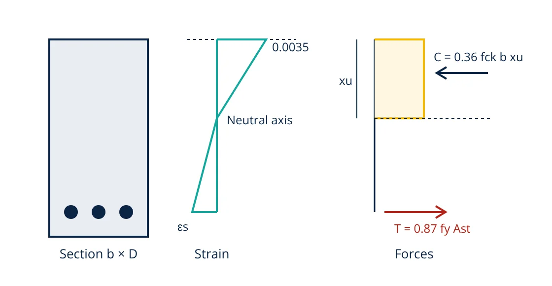
- The maximum compressive strain in concrete at failure is 0.0035.
- The tensile strength of concrete is ignored.
- The design stress in concrete follows a parabolic and rectangular curve with a peak of 0.67 fck / 1.5 = 0.446 fck.
- Steel stress is found from its design stress strain curve, with a maximum of fy / 1.15 = 0.87 fy.
- To ensure ductile failure, the strain in tension steel at failure must be at least 0.87 fy / Es + 0.002.
Integrating the concrete stress gives a compression force of 0.36 fck b xu acting at 0.42 xu from the top, where b is the width and xu the neutral axis depth.
Equating C and T gives the neutral axis depth, and the moment of the couple gives the moment of resistance:
IS 456 limits xu to xu,max: 0.53d for Fe250, 0.48d for Fe415 and 0.46d for Fe500. A section with xu below xu,max is under-reinforced and fails by steel yielding first, with warning. The limiting moment for Fe415 works out to about 0.138 fck b d².
- Given
- A rectangular beam 230 mm wide with effective depth d = 450 mm, M20 concrete and Fe415 steel. Factored design moment Mu = 100 kN·m.
- Find
- The limiting moment and the area of tension steel required.
- Assumptions
- Singly reinforced section; IS 456 stress block; moment already includes the 1.5 load factor.
- Solution
- Mu,lim = 0.138 × 20 × 230 × 450² = 128.5 × 10⁶ N·mm = 128.5 kN·m. Since 100 is less than 128.5, a singly reinforced section is adequate
Ast = (0.5 fck / fy) [1 − √(1 − 4.6 Mu / (fck b d²))] b d
4.6 × 100 × 10⁶ / (20 × 230 × 450²) = 0.494
Ast = (0.5 × 20 / 415) × (1 − √0.506) × 230 × 450 = 0.0241 × 0.289 × 103,500 = 720 mm² - Answer
- Mu,lim = 128.5 kN·m; provide at least 720 mm² of steel, for example 4 bars of 16 mm (804 mm²)
- Limitations
- Check minimum and maximum steel, shear, development length, deflection (span to depth ratio) and cover for the exposure condition before finalising.
Limit state design compared with working stress method
The working stress method treats concrete and steel as elastic and keeps stresses under service loads below permissible values, using a modular ratio to combine the two materials. It is simple but does not show the real margin against collapse, because materials do not stay elastic up to failure, and it applies one overall factor regardless of whether the uncertainty lies in the load or the material. Limit state design looks at the actual failure condition with inelastic material behaviour, applies separate factors to loads and materials, and checks serviceability separately. The result is usually a more economical and more consistent level of safety. IS 456 keeps the working stress method in an annex, but limit state design is the method generally used.
Serviceability checks
- Deflection: IS 456 limits the final deflection to span/250, and controls it simply by basic span to effective depth ratios: 7 for cantilevers, 20 for simply supported and 26 for continuous spans up to 10 m, modified for steel percentage and compression steel.
- Cracking: controlled by bar spacing rules and by limiting crack widths (generally 0.3 mm for most exposures).
- Durability: minimum grade, maximum water cement ratio, minimum cement content and nominal cover all depend on the exposure class.
Where limit state design starts
The moments and shears used in design come from structural analysis, such as shear force and bending moment diagrams for beams. Material quality depends on the type of cement and good concreting practice, and the foundations that carry the structure are designed from the bearing capacity of soil.
Frequently asked questions
What is the difference between working stress method and limit state method?
The working stress method keeps stresses under service loads below allowable values, using one overall factor of safety on material strength. The limit state method checks the structure at collapse with factored loads and reduced material strengths, and separately checks serviceability such as deflection and cracking. IS 456 uses limit state design as the main method.
Why is the partial safety factor for concrete higher than for steel?
Concrete strength depends on site batching, placing, compaction and curing, so it varies more than factory-produced reinforcing steel. IS 456 therefore uses 1.5 for concrete and 1.15 for steel at the limit state of collapse.
What is an under-reinforced section?
A section in which the tension steel yields before the concrete reaches its crushing strain. Failure is gradual with large deflection and visible cracking, which gives warning. Limiting the neutral axis depth to xu,max ensures beams are designed as under-reinforced or balanced.
References
- IS 456:2000 Plain and Reinforced Concrete, Code of Practice (Fourth Revision), Bureau of Indian Standards
- SP 16:1980 Design Aids for Reinforced Concrete to IS 456, Bureau of Indian Standards
- S. Unnikrishna Pillai and D. Menon, Reinforced Concrete Design, 3rd ed., McGraw-Hill Education
- EN 1992-1-1:2004 Eurocode 2: Design of concrete structures, Part 1-1: General rules and rules for buildings
Get one engineering email a week
New articles, worked examples and study notes every week. Free, no spam, unsubscribe any time.