Types of Beams and Supports in Structures
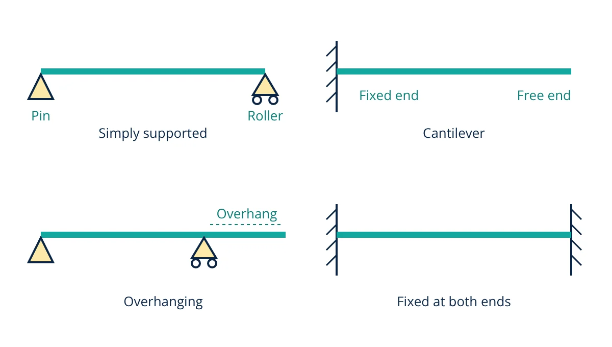
The main types of beams are classified by how they are supported: simply supported (pin at one end, roller at the other), cantilever (fixed at one end, free at the other), overhanging, fixed (both ends built in), propped cantilever and continuous (more than two supports). The support type decides the reactions, the bending moment pattern and the deflection, so it is the first choice in any beam design.
A beam is a structural member that carries loads applied across its length and transfers them to its supports by bending and shear. Floors, bridges, crane girders, lintels and machine frames all contain beams. This guide explains the support types, the common types of beams, the difference between determinate and indeterminate beams, and how much the support condition changes the bending moment for the same load.
Types of supports
Every beam type is defined by its supports. In a two-dimensional (plane) structure, each support can resist some combination of horizontal force, vertical force and moment.
| Support | Restrains | Allows | Reactions |
|---|---|---|---|
| Roller | Movement perpendicular to the surface | Movement along the surface, rotation | 1 force |
| Pin (hinge) | Horizontal and vertical movement | Rotation | 2 forces |
| Fixed (built in) | Horizontal and vertical movement, rotation | Nothing | 2 forces and 1 moment |
Real supports only approximate these ideals. A steel beam bolted through its web to a column is usually treated as pinned, while a beam welded fully to a stiff column, or cast monolithically into a concrete wall, is closer to fixed. Bearings on bridges are designed as rollers so the deck can expand with temperature.
Common types of beams
Simply supported beam
A beam resting on a pin at one end and a roller at the other. It has three reaction components, which can be found from the three equations of static equilibrium. The beam is free to rotate at both ends, so the bending moment is zero there and largest near midspan. The bottom fibres are in tension under downward load. Lintels, many timber joists and single span bridge girders are designed this way.
Cantilever beam
A beam fixed at one end and free at the other. The fixed support provides a vertical reaction, a horizontal reaction and a moment. The largest bending moment and shear occur at the fixed end, and the top fibres are in tension. Balconies, canopies, cantilever retaining walls and crane jibs are examples.
Overhanging beam
A simply supported beam that extends beyond one or both supports. The overhang produces a negative (hogging) moment over the support, which reduces the positive (sagging) moment in the main span. A point of contraflexure, where the moment changes sign, lies between them.
Fixed beam
A beam built in at both ends, so neither end can rotate. It has six reaction components in total, so it is statically indeterminate. End moments are hogging and the midspan moment is sagging and much smaller than in a simply supported beam.
Propped cantilever
A cantilever with an extra support (usually a roller) at the free end. It has four reaction components and is indeterminate to the first degree.
Continuous beam
A beam running over three or more supports. Most reinforced concrete floor beams and many multi-span bridges are continuous. Continuity lowers span moments but creates hogging moments over interior supports. Moment distribution, slope deflection or matrix methods are used to analyse them.
Determinate and indeterminate beams
A plane beam has three independent equations of equilibrium: ΣFx = 0, ΣFy = 0 and ΣM = 0.
- Statically determinate: exactly three independent reaction components, all found from statics alone. Simply supported, cantilever and overhanging beams belong here.
- Statically indeterminate: more reactions than equations. The extra unknowns are found from compatibility of deflections and rotations. Fixed, propped cantilever and continuous beams belong here. The degree of indeterminacy is the number of reactions minus three (for a beam with no internal hinges).
Indeterminate beams are stiffer and have redundancy, but they attract stresses from settlement of supports and temperature change, which determinate beams avoid.
Bending moment and deflection by beam type
For a beam of span L carrying a uniformly distributed load w (force per unit length), standard results from beam tables are:
| Beam type | Maximum bending moment | Location | Maximum deflection |
|---|---|---|---|
| Simply supported | wL² / 8 | Midspan | 5wL⁴ / 384EI |
| Cantilever | wL² / 2 | Fixed end | wL⁴ / 8EI |
| Fixed at both ends | wL² / 12 (hogging) | Supports | wL⁴ / 384EI |
| Fixed at both ends | wL² / 24 (sagging) | Midspan | Same as above |
For a simply supported beam the maximum moment is:
The full method for drawing these diagrams is in shear force and bending moment diagrams explained.
- Given
- A beam of span L = 6 m carries a uniformly distributed load w = 10 kN/m (including self weight).
- Find
- The reactions and maximum bending moment if the beam is (a) simply supported, (b) a cantilever, (c) fixed at both ends.
- Assumptions
- Ideal supports, prismatic beam, linear elastic behaviour, no axial load.
- Solution
- Total load W = wL = 10 × 6 = 60 kN
(a) Reactions = W / 2 = 30 kN each. Mmax = wL² / 8 = 10 × 36 / 8 = 45 kN·m at midspan
(b) Vertical reaction = 60 kN at the fixed end. Mmax = wL² / 2 = 10 × 36 / 2 = 180 kN·m at the fixed end
(c) Vertical reactions = 30 kN each. End moments = wL² / 12 = 10 × 36 / 12 = 30 kN·m (hogging). Midspan moment = wL² / 24 = 10 × 36 / 24 = 15 kN·m (sagging) - Answer
- Maximum moment 45 kN·m simply supported, 180 kN·m as a cantilever, 30 kN·m fixed at both ends
- Limitations
- Real end connections are rarely fully fixed or perfectly pinned; partial fixity gives values between cases (a) and (c). Design codes may require moment redistribution limits and load combinations not considered here.
The same load gives a moment four times larger as a cantilever than as a simply supported beam, and the fixed beam carries the lowest peak moment. That is why cantilevers need deep sections at the root and why designers use continuity wherever practical.
Choosing a beam type
- Span and loads: long spans favour continuous or fixed beams to control deflection.
- Connections: simple shear connections in steel frames are cheaper than moment connections, so steel buildings often use simply supported beams. Common profiles are compared in types of steel sections.
- Construction method: cast in place concrete is naturally continuous; precast units are usually simply supported.
- Movement: determinate beams accommodate settlement and thermal movement without extra stress, which is valuable on poor soil and in bridges. See types of bridges.
- Design method: concrete beams are sized by the limit state approach described in limit state design of RCC.
Related reading
Frequently asked questions
Which type of beam is strongest?
For the same span, section and load, a beam fixed at both ends has the smallest maximum bending moment and deflection, because the end restraints share the load. Under a uniform load its largest moment is one third of that in a simply supported beam and its midspan deflection is one fifth.
What is the difference between a pin support and a roller support?
A pin (hinge) support prevents movement in both horizontal and vertical directions but allows rotation, so it provides two reaction components. A roller allows horizontal movement and rotation and provides only one reaction, perpendicular to the surface it rolls on.
Why are most beams in buildings continuous?
Monolithic concrete floors and beams cast over several supports act as continuous members. Continuity reduces the midspan moments and deflections compared with separate simply supported spans, so smaller sections can be used, at the cost of hogging moments over the supports that need top reinforcement.
References
- R. C. Hibbeler, Structural Analysis, 10th ed., Pearson
- J. M. Gere and B. J. Goodno, Mechanics of Materials, 9th ed., Cengage
- American Institute of Steel Construction, Steel Construction Manual, 15th ed., Part 3: Beam Diagrams and Formulas
- C. H. Norris, J. B. Wilbur and S. Utku, Elementary Structural Analysis, 4th ed., McGraw-Hill
Get one engineering email a week
New articles, worked examples and study notes every week. Free, no spam, unsubscribe any time.