Satellite Subsystems Explained
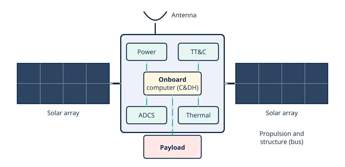
Satellite subsystems are the functional blocks of a spacecraft. The payload performs the mission, and the bus supports it with structure, electrical power, thermal control, attitude determination and control, propulsion, telemetry, tracking and command, and command and data handling. All must survive launch, vacuum, radiation and extreme temperatures for years without repair.
A satellite is a small, self contained world that must provide its own power, temperature control, pointing and communications for years in an environment where no repair is possible. Designing it means balancing mass, power, volume, cost and reliability across all subsystems, guided by the mission and orbit, as discussed in GEO vs MEO vs LEO satellites.
Payload
The reason the satellite exists: optical or radar imagers for Earth observation, communication transponders and antennas, navigation signal generators, or scientific instruments. Payload requirements drive pointing accuracy, power, data rate and thermal stability.
Structure and mechanisms
The structure holds everything together and survives launch, where loads reach several g with intense vibration and acoustic noise. Common materials are aluminium honeycomb panels, carbon fibre composites and titanium fittings. Mechanisms deploy solar arrays, antennas and booms, and include hinges, release devices and drive motors. Design is verified by analysis such as finite element analysis and by vibration and shock testing.
Electrical power subsystem (EPS)
- Solar arrays: multi-junction gallium arsenide cells with efficiencies around 30% convert sunlight (about 1361 W/m² near Earth) into electricity.
- Batteries: lithium-ion cells store energy for eclipses.
- Power conditioning and distribution: regulators, converters and switches deliver protected power to each subsystem, using techniques similar to the buck converter.
Some deep space missions use radioisotope thermoelectric generators where sunlight is too weak.
Thermal control
In space, sunlit surfaces can exceed 100 °C while shaded ones fall below −100 °C. Electronics typically need about −20 to +50 °C and batteries a narrower range. Thermal control uses:
- Passive methods: multi-layer insulation (MLI) blankets, surface coatings and paints with chosen absorptivity and emissivity, radiators, heat pipes.
- Active methods: electrical heaters with thermostats, loop heat pipes, and pumped fluid loops on large spacecraft.
All heat must finally be radiated to space, following the Stefan-Boltzmann law, since there is no air for convection, as described in modes of heat transfer.
Attitude determination and control (ADCS)
The satellite must point its payload, antennas and solar arrays in the right directions.
- Sensors: sun sensors, Earth horizon sensors, magnetometers, gyroscopes and star trackers (most accurate, arcsecond level).
- Actuators: reaction wheels and control moment gyros exchange momentum with the spacecraft; magnetorquers use Earth’s magnetic field to dump momentum in LEO; thrusters provide large torques.
- Control software combines sensor data (for example with Kalman filters) and commands actuators.
Propulsion
Propulsion raises orbits after launch, maintains position (station keeping), avoids collisions and deorbits at end of life.
- Chemical: monopropellant hydrazine or green propellants, and bipropellant systems for large orbit changes.
- Electric: Hall effect thrusters and gridded ion engines with very high specific impulse but low thrust, widely used for GEO station keeping and LEO constellations.
- Cold gas for small satellites.
Telemetry, tracking and command (TT&C)
Radio links to ground stations, typically in S band or X band, receive commands, send housekeeping telemetry and allow ranging to determine orbit. Payload data often uses a separate high rate downlink. Link design uses modulation techniques and error correction suited to the long, noisy space channel.
Command and data handling (C&DH)
The onboard computer runs flight software that schedules operations, processes commands, monitors health, stores data, manages fault detection and recovery (switching to safe mode when something goes wrong), and controls the other subsystems through data buses such as SpaceWire, CAN or MIL-STD-1553. Radiation tolerant electronics and error correcting memory protect against single event upsets.
Power budget
Solar arrays must supply the satellite in sunlight and recharge batteries for eclipse:
where P_e and P_d are loads in eclipse and daylight, T_e and T_d their durations, and X_e, X_d path efficiencies (typically about 0.6 to 0.65 and 0.8 to 0.85).
- Given
- A LEO satellite with a 95 minute orbit spends 35 minutes in eclipse. It needs 120 W in daylight and 100 W in eclipse. Path efficiencies are X_d = 0.85 and X_e = 0.65. Battery depth of discharge limit is 25% with a bus voltage of 28 V.
- Find
- Required solar array output at end of life and battery capacity.
- Assumptions
- Constant loads; simplified SMAD method; battery discharge efficiency included in X_e.
- Solution
- T_d = 95 − 35 = 60 min
P_sa = [(100 × 35 ÷ 0.65) + (120 × 60 ÷ 0.85)] ÷ 60 = (5385 + 8471) ÷ 60 = 231 W
Eclipse energy = 100 W × 35 ÷ 60 h = 58.3 Wh
Battery capacity = 58.3 ÷ 0.25 = 233 Wh, or 233 ÷ 28 ≈ 8.3 Ah - Answer
- Solar arrays must deliver about 231 W at end of life, with a battery of about 233 Wh (8.3 Ah at 28 V)
- Limitations
- Array degradation from radiation, sun angle, temperature and margins increase the beginning of life array size.
Key formulas for satellite subsystems
| Quantity | Formula | Symbols and units |
|---|---|---|
| Solar array power (end of life) | P_sa = [(P_e T_e ÷ X_e) + (P_d T_d ÷ X_d)] ÷ T_d | P loads (W), T durations (min), X path efficiencies |
| Daylight duration | T_d = T_orbit − T_e | min |
| Eclipse energy | E = P_e × T_e | Wh, with T_e in hours |
| Battery capacity | C = E ÷ DoD | DoD = allowed depth of discharge |
| Battery amp hours | Ah = Wh ÷ V_bus | V_bus = bus voltage (V) |
Redundancy and reliability
Because repair in orbit is almost never possible, critical units are duplicated or cross strapped so that a backup can take over. Typical examples are redundant onboard computers, two receivers and transmitters for TT&C, extra reaction wheels in a skewed arrangement, and redundant thruster branches. Components are selected for radiation tolerance, and fault detection, isolation and recovery software decides automatically how to respond to failures.
Integration and testing of satellite subsystems
Subsystems are integrated and tested together through functional tests, vibration and acoustic tests that simulate launch, thermal vacuum cycling, electromagnetic compatibility checks and end to end communication tests with ground stations. Systems engineering, following standards such as ECSS, manages interfaces, budgets for mass, power and data, and risks across all satellite subsystems, so that the spacecraft works first time in orbit.
Satellite subsystems interview and viva questions
- What is the difference between the payload and the bus? The payload performs the mission, such as imaging or communications; the bus provides the structure, power, thermal control, pointing, propulsion, communications and computing that support it.
- Why must all heat be radiated in space? There is no air for convection, so heat can leave the spacecraft only by radiation from surfaces such as radiators.
- How do reaction wheels control attitude? They exchange angular momentum with the spacecraft: speeding a wheel up turns the satellite the opposite way.
- Why are magnetorquers used in LEO? They push against Earth’s magnetic field to remove stored momentum from the reaction wheels without using propellant.
- What happens in safe mode? The onboard software detects a fault, switches to a simple, power positive attitude and waits for commands from the ground.
Frequently asked questions
What is the difference between the payload and the bus?
The payload is the equipment that performs the mission, such as cameras, communication transponders or scientific instruments. The bus (platform) is everything that supports the payload: structure, power, thermal control, attitude control, propulsion, communications for command and telemetry, and onboard computers.
Why do satellites need batteries if they have solar panels?
Satellites in low Earth orbit spend up to about a third of each orbit in Earth's shadow (eclipse), when solar arrays produce no power. Batteries store energy during sunlight and supply the satellite during eclipse. GEO satellites face eclipses of up to about 72 minutes near the equinoxes.
What is a CubeSat?
A CubeSat is a standardised small satellite built from 10 cm cubic units (1U), commonly 1U, 3U, 6U or 12U. Standard sizes and deployers lower launch costs, and commercial off the shelf subsystems make CubeSats popular for universities, technology demonstrations and Earth observation constellations.
References
- J. R. Wertz, D. F. Everett and J. J. Puschell (eds.), Space Mission Engineering: The New SMAD, Microcosm Press, 2011
- P. Fortescue, G. Swinerd and J. Stark (eds.), Spacecraft Systems Engineering, 4th ed., Wiley
- ECSS-E-ST-10C, Space engineering: System engineering general requirements, European Cooperation for Space Standardization
- CubeSat Design Specification Rev. 14, California Polytechnic State University
- NASA, State of the Art Small Spacecraft Technology, NASA Ames, 2024
Get one engineering email a week
New articles, worked examples and study notes every week. Free, no spam, unsubscribe any time.