Safety Instrumented System (SIS) Basics
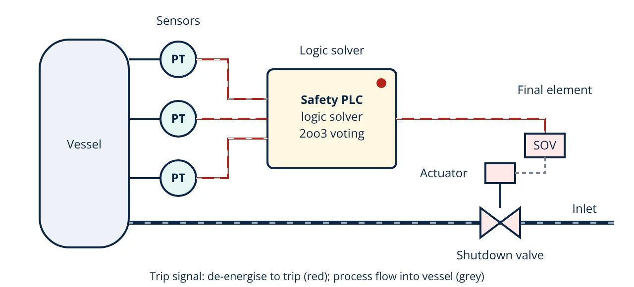
A safety instrumented system (SIS) is an independent automatic protection system that detects a dangerous process condition with sensors, decides in a safety logic solver and drives final elements such as shutdown valves to a safe state. It implements one or more safety instrumented functions, each designed to a required SIL under IEC 61511.
A safety instrumented system is the last automatic layer that stops a process before a hazard such as overpressure, overfilling or a runaway reaction becomes an accident. It sits behind the basic process control system (BPCS) and the operator, and in front of mechanical devices such as relief valves. This article explains what an SIS is made of, how it is designed and tested, and how its reliability is calculated.
What a safety instrumented system does
The BPCS keeps the process at its normal operating point. The SIS does nothing during normal operation. It watches for one specific abnormal condition per function, and when that condition is reached it takes a fixed action that brings the process to a defined safe state, for example closing a feed valve, stopping a pump or depressurising a vessel.
IEC 61511-1 defines three related terms:
- Safety instrumented system (SIS): the complete system of sensors, logic solvers and final elements.
- Safety instrumented function (SIF): one protective action with a stated trip point, response time and safe state, such as “close XV-101 when PT-101 exceeds 18 barg”.
- Safety integrity level (SIL): the required reliability of each SIF, explained in detail in safety integrity level (SIL).
The need for each SIF and its target SIL usually come from a hazard study such as a HAZOP followed by layer of protection analysis (LOPA).
Parts of a safety instrumented system
Sensors
Transmitters or switches measure the hazardous variable: pressure, level, temperature, flow, gas concentration or flame. SIS sensors are separate from the BPCS sensors, are selected as suitable for the SIL (by certification to IEC 61508 or by documented prior use), and are often redundant. Good pressure measurement practice, such as correct impulse lines and range selection, matters as much as the device rating.
Logic solver
The logic solver is usually a safety PLC certified to IEC 61508, with internal diagnostics, redundant processors and a protected application program. Relay and solid state logic are also used for simple systems. It compares inputs with trip points, applies voting, and drives outputs. It must be separate from the control system; the differences between a control system and a safety system are explained in PLC vs DCS.
Final elements
Final elements do the physical work: a solenoid valve vents the actuator air and a spring return shutdown valve closes, or a contactor or breaker stops a motor. In most SIS reliability studies the final element contributes the largest share of the probability of failure on demand, because valves can stick after long periods in one position.
Design principles
Independence and separation
The SIS should not share sensors, logic or valves with the BPCS unless the sharing has been analysed. A failed BPCS transmitter can be the cause of the upset, and the same transmitter cannot then be trusted to detect it.
Fail safe action
Most SIS loops are de-energise to trip: the healthy state is energised, and loss of signal, power or air moves the final element to the safe position. Broken wires and power failures therefore cause a spurious trip rather than a hidden loss of protection.
Voting architectures
Redundant devices are combined by voting, written MooN (M out of N must vote to trip):
| Architecture | Trips when | Strength | Weakness |
|---|---|---|---|
| 1oo1 | the single device trips | simple, cheap | one dangerous failure disables the function |
| 1oo2 | either of two trips | lower PFDavg | more spurious trips |
| 2oo2 | both of two trip | fewer spurious trips | higher PFDavg than 1oo2 |
| 2oo3 | any two of three trip | low PFDavg and few spurious trips | more devices to buy and test |
Redundancy is limited by common cause failures, such as plugged impulse lines or the same software fault in identical devices. The beta factor model in IEC 61508-6 represents this as a fraction β of dangerous failures that affect all channels at once.
The IEC 61511 safety lifecycle
IEC 61511 manages the SIS through a lifecycle so that errors in specification, which cause many failures, are caught early:
- Hazard and risk assessment, giving the list of SIFs and their target SILs.
- Safety requirements specification (SRS): trip points, safe states, response times, voting, bypass rules, proof test intervals and spurious trip targets.
- Design and engineering, including SIL verification of each SIF.
- Installation, commissioning and validation (site acceptance testing of every function end to end).
- Operation and maintenance, including proof testing, bypass control and management of change.
- Modification and decommissioning under the same discipline.
Functional safety assessments and audits at defined stages confirm the work was done as planned.
Reliability of a safety instrumented system
A low demand SIF is judged by its average probability of failure on demand (PFDavg). Dangerous undetected failures (rate λDU) stay hidden until a proof test finds them, so the probability grows during each test interval TI. The simplified equations in IEC 61508-6 and ISA-TR84.00.02, ignoring repair time and diagnostics, are:
The risk reduction factor is RRF = 1 ÷ PFDavg. A SIF must also meet architectural constraints (hardware fault tolerance) and systematic capability, not just the PFDavg number. Failure rate data often comes from the same reliability concepts used in MTBF, MTTR and availability.
- Given
- A high pressure SIF uses two transmitters voted 1oo2, each with λDU = 0.005 per year and β = 0.05; a certified safety PLC with PFDavg = 1.0 × 10⁻⁴ from the vendor; and one shutdown valve assembly with λDU = 0.02 per year. All devices are proof tested every year (TI = 1 year). The target is SIL 2.
- Find
- PFDavg and RRF of the SIF, and the effect of testing the valve every 6 months.
- Assumptions
- Simplified equations above; perfect proof tests; repair time and diagnostic coverage ignored; failure rates are illustrative, not vendor data.
- Solution
- Sensors: (0.005 × 1)² ÷ 3 + 0.05 × 0.005 × 1 ÷ 2 = 8.3 × 10⁻⁶ + 1.25 × 10⁻⁴ = 1.33 × 10⁻⁴
Logic solver: 1.0 × 10⁻⁴
Valve: 0.02 × 1 ÷ 2 = 0.010
Total PFDavg = 0.000133 + 0.0001 + 0.010 = 0.0102, RRF = 1 ÷ 0.0102 = 97.7
With valve TI = 0.5 year: valve = 0.02 × 0.5 ÷ 2 = 0.005; total = 0.00523, RRF = 191 - Answer
- With annual testing PFDavg ≈ 0.0102 (RRF ≈ 98), which is only SIL 1. Testing the valve every 6 months gives PFDavg ≈ 0.0052 (RRF ≈ 191), which meets SIL 2.
- Limitations
- Real verification uses vendor or industry failure data, diagnostic coverage, repair time, imperfect proof test coverage and architectural constraints. A second valve (1oo2) is another option.
The example shows a typical result: the common cause term dominates the redundant sensors, and the single valve dominates the whole function.
Key formulas for safety instrumented system design
| Quantity | Formula | Symbols and units |
|---|---|---|
| PFDavg, 1oo1 | λDU × TI ÷ 2 | λDU = dangerous undetected failure rate per year, TI = proof test interval in years |
| PFDavg, 1oo2 | (λDU × TI)² ÷ 3 + β × λDU × TI ÷ 2 | β = common cause fraction (dimensionless) |
| PFDavg of a SIF | PFD_sensor + PFD_logic + PFD_final | sum of subsystem PFDavg values |
| Risk reduction factor | RRF = 1 ÷ PFDavg | dimensionless |
Operation, testing and bypasses
An SIS degrades silently, so operation matters as much as design:
- Proof tests at the interval in the SRS find dangerous undetected failures. A full test moves the valve and checks stroke time; partial stroke testing can find some valve faults between full tests.
- Bypasses and overrides are controlled by permit, time limited, alarmed and logged, with compensating measures during the bypass.
- Demand and trip records are reviewed to compare actual failure rates with design assumptions.
- Management of change applies to trip points, logic and device replacements.
Failure logic for complex systems can be checked with fault tree analysis.
Safety instrumented system interview and viva questions
- What are the three subsystems of a safety instrumented function? Sensors that detect the hazardous condition, a logic solver that decides to trip, and final elements such as shutdown valves that bring the process to a safe state.
- Why must the SIS be independent of the BPCS? A BPCS failure may be the initiating cause of the hazard, so a protection layer that shares the failed component cannot be relied on to stop it.
- What is the advantage of 2oo3 voting? It tolerates one dangerous failure and also avoids a trip from one spurious signal, giving low PFDavg and a low spurious trip rate.
- How does the proof test interval affect PFDavg? For a 1oo1 device PFDavg is λDU × TI ÷ 2, so halving the test interval halves the average probability of failure on demand.
- What is a safety requirements specification? It is the IEC 61511 document that defines each SIF: trip point, safe state, response time, voting, required SIL, test interval and bypass rules.
Frequently asked questions
Can the basic process control system also act as the SIS?
Normally no. IEC 61511 expects the SIS to be independent of the basic process control system so that a single failure cannot both cause the hazard and disable the protection. Limited sharing is allowed only when it is analysed and justified, and the BPCS itself is usually credited as a separate protection layer in LOPA.
What is the difference between a SIS and a SIF?
A safety instrumented function (SIF) is one specific protective action, such as closing an inlet valve on high-high pressure, with its own required SIL. The safety instrumented system (SIS) is the whole set of hardware and software, sensors, logic solvers and final elements, that carries out one or more SIFs.
Why are most SIS circuits de-energise to trip?
In a de-energise to trip design, loss of power, a broken wire or a failed output removes the signal and moves the final element to its safe state. Common failures therefore become safe failures. Energise to trip designs exist, for example some fire and gas systems, but then line monitoring and power supply integrity become critical.
References
- IEC 61511-1:2016+A1:2017, Functional safety: Safety instrumented systems for the process industry sector, Part 1: Framework, definitions, system, hardware and application programming requirements
- IEC 61508-6:2010, Functional safety of electrical/electronic/programmable electronic safety-related systems, Part 6: Guidelines on the application of IEC 61508-2 and IEC 61508-3
- ISA-TR84.00.02-2015, Safety Integrity Level (SIL) Verification of Safety Instrumented Functions, International Society of Automation
- P. Gruhn and H. Cheddie, Safety Instrumented Systems: Design, Analysis, and Justification, 2nd ed., ISA, 2006
- CCPS, Guidelines for Safe and Reliable Instrumented Protective Systems, AIChE and Wiley, 2007
Get one engineering email a week
New articles, worked examples and study notes every week. Free, no spam, unsubscribe any time.