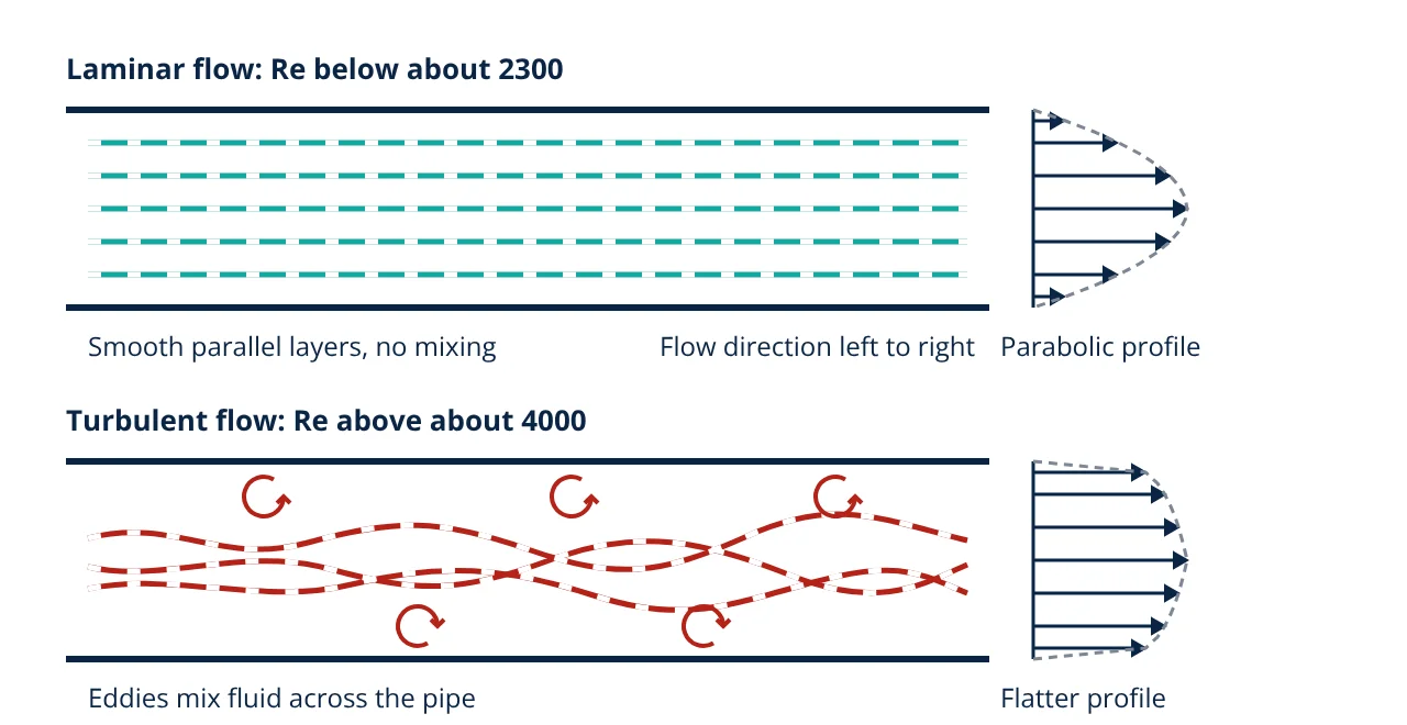
Reynolds Number: Laminar and Turbulent Flow
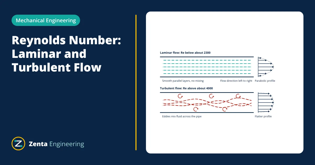
The Reynolds number is a dimensionless ratio of inertial forces to viscous forces in a moving fluid, Re = ρVD/μ. It predicts the flow regime. In a circular pipe, flow is laminar below about 2300, transitional from about 2300 to 4000 and turbulent above about 4000, which sets friction, pressure drop and heat transfer.
The Reynolds number is the first quantity an engineer calculates for almost any flow problem. It tells you whether fluid in a pipe, duct or around a body moves in smooth layers or in chaotic eddies, and that single answer decides which friction factor, heat transfer correlation and drag coefficient to use. This article explains the definition, the physical meaning, the critical values and how to use it in practice.
What the Reynolds number means
Osborne Reynolds published his classic pipe experiments in 1883. He injected a thin filament of dye into water flowing through a glass tube. At low speed the dye stayed as a straight, sharp line. As the speed increased, the filament began to waver and then suddenly broke up and mixed across the whole tube. Reynolds showed that the change did not depend on velocity, diameter or viscosity alone, but on one combination of them.
That combination is:
where ρ is fluid density (kg/m³), V is the mean velocity (m/s), D is a characteristic length such as pipe diameter (m), μ is dynamic viscosity (Pa·s) and ν = μ/ρ is kinematic viscosity (m²/s).
Physically, the numerator measures the momentum the fluid carries (inertia), which tends to amplify small disturbances. The denominator measures viscous friction, which damps them out. At low Re, viscosity wins and any disturbance dies away, giving orderly laminar flow. At high Re, inertia wins, disturbances grow and the flow becomes turbulent.
Laminar, transitional and turbulent flow
For fully developed flow in a smooth circular pipe, standard textbooks such as Cengel and Cimbala use these engineering limits:
| Pipe flow regime | Reynolds number | Behaviour |
|---|---|---|
| Laminar | below about 2300 | Smooth layers, dye stays as a line, parabolic profile |
| Transitional | about 2300 to 4000 | Flow switches between laminar and turbulent bursts |
| Turbulent | above about 4000 | Random eddies, strong mixing, flatter profile |
These limits are not sharp physical constants. Reynolds himself, and later researchers, kept pipe flow laminar to much higher values by using very smooth inlets and vibration free rigs. In real piping, with rough walls, fittings, pumps and vibration, flow usually becomes turbulent close to the lower value.
Laminar flow characteristics
In laminar pipe flow the velocity profile is a parabola. The centreline velocity is twice the mean velocity, and momentum moves across the pipe only by molecular viscosity. The Darcy friction factor is known exactly:
so pressure drop is directly proportional to velocity. Laminar flow is common with viscous oils, in small tubes, in blood capillaries and in lubrication films, discussed in types of lubrication.
Turbulent flow characteristics
Turbulent flow carries swirling eddies of many sizes. They transport momentum and heat across the pipe far faster than viscosity alone, so the mean profile is flatter, often approximated by a one seventh power law, with a steep gradient in a thin layer near the wall. The friction factor depends on both Re and the relative roughness ε/D and is read from the Moody chart or the Colebrook equation:
Most water, steam and air flows in industrial pipes and ducts are turbulent.
Choosing the characteristic length
The value of Re depends on the length you choose, so each geometry has its own convention and its own critical value:
- Circular pipe: D is the inside diameter.
- Non circular duct: use the hydraulic diameter D_h = 4A/P, where A is flow area and P is wetted perimeter. For a circular pipe D_h equals D.
- Flat plate boundary layer: use distance x from the leading edge. Transition on a smooth plate is usually taken at Re_x of about 5 × 10⁵.
- Flow around a sphere or cylinder: use the body diameter. This governs drag and vortex shedding, as covered in drag force on aircraft.
Never compare a Reynolds number calculated with one length against a critical value defined with another.
Entrance length
Flow entering a pipe needs some distance before the velocity profile stops changing. This is the hydrodynamic entrance length. Cengel and Cimbala give approximately:
For turbulent flow the entrance length is much shorter and is often taken as about 10 pipe diameters. This is why flowmeters need straight runs of pipe upstream, and why laminar flow in a long oil line may never become fully developed in a short heat exchanger tube.
Why the Reynolds number matters in design
- Pressure drop and pump sizing: Re selects the friction factor for the Darcy-Weisbach equation, which gives the head loss a pump must overcome. See the centrifugal pump working principle and the Bernoulli equation energy balance.
- Heat transfer: convection coefficients are given as Nusselt number correlations in terms of Re and Prandtl number. Turbulent flow transfers far more heat, which is why exchanger tubes are designed for turbulent velocities; see modes of heat transfer and heat exchanger types.
- Flow measurement: discharge coefficients of orifice plates and venturis, and the K factor of many meters, vary with Re.
- Model testing: two geometrically similar flows behave the same way when their Reynolds numbers match. This dynamic similarity lets wind tunnel and water channel models predict full size results.
- Given
- Water at 20 °C flows at a mean velocity of 1.5 m/s in a smooth pipe of 50 mm inside diameter. Properties at 20 °C: ρ = 998 kg/m³, μ = 1.002 × 10⁻³ Pa·s.
- Find
- The Reynolds number and flow regime, and the highest mean velocity that would keep the flow laminar.
- Assumptions
- Fully developed, steady, incompressible flow; laminar limit taken as Re = 2300.
- Solution
- Re = ρVD / μ = 998 × 1.5 × 0.05 / 0.001002 = 74,700
74,700 is far above 4000, so the flow is turbulent.
ν = μ / ρ = 0.001002 / 998 = 1.004 × 10⁻⁶ m²/s
V_max laminar = 2300 × ν / D = 2300 × 1.004 × 10⁻⁶ / 0.05 = 0.046 m/s - Answer
- Re is about 74,700, so the flow is turbulent. The water would need to move slower than about 0.046 m/s (46 mm/s) to stay laminar.
- Limitations
- Viscosity changes strongly with temperature, so recalculate Re at the actual fluid temperature. The 2300 limit is an engineering value; disturbances and fittings can trigger turbulence earlier.
The result is typical: water at ordinary pipe velocities is almost always turbulent, while laminar flow needs very low speed, a small tube or a much more viscous fluid.
Key formulas for the Reynolds number
| Quantity | Formula | Symbols and units |
|---|---|---|
| Reynolds number | Re = ρVD / μ = VD / ν | ρ in kg/m³, V in m/s, D in m, μ in Pa·s, ν in m²/s |
| Kinematic viscosity | ν = μ / ρ | m²/s |
| Hydraulic diameter | D_h = 4A / P | A = flow area in m², P = wetted perimeter in m |
| Laminar friction factor | f = 64 / Re | Darcy friction factor, dimensionless |
| Laminar entrance length | L_h ≈ 0.05 Re D | L_h and D in m |
| Flat plate Reynolds number | Re_x = ρVx / μ | x = distance from leading edge in m; transition near 5 × 10⁵ |
Common mistakes
- Using the pipe outside diameter instead of the inside diameter.
- Mixing dynamic viscosity (Pa·s) with kinematic viscosity (m²/s), or using centipoise without converting (1 cP = 0.001 Pa·s).
- Taking viscosity at the wrong temperature, especially for oils, whose viscosity can change several times over a modest temperature range.
- Applying the pipe limit of 2300 to a flat plate, a sphere or an open channel.
Reynolds number interview and viva questions
- What does the Reynolds number physically represent? It is the ratio of inertial forces to viscous forces in a flow. A high value means inertia dominates and disturbances grow into turbulence.
- What are the laminar and turbulent limits for pipe flow? Flow in a circular pipe is usually laminar below about 2300, transitional from 2300 to 4000 and turbulent above about 4000.
- What is the friction factor for laminar pipe flow? The Darcy friction factor is f = 64/Re, independent of wall roughness.
- What length is used for a non circular duct? The hydraulic diameter, four times the flow area divided by the wetted perimeter.
- Why is Reynolds number matching important in model testing? Geometrically similar flows with the same Reynolds number are dynamically similar, so forces and flow patterns measured on a model scale correctly to the full size object.
Related reading
Frequently asked questions
Is the Reynolds number dimensionless?
Yes. Density times velocity times length, divided by dynamic viscosity, has no units because all the units cancel. That is why the same limits apply to water, oil and air in pipes of any size, as long as consistent units are used.
What Reynolds number is laminar flow in a pipe?
For flow in a smooth circular pipe, engineering texts take flow as laminar below a Reynolds number of about 2300, transitional between about 2300 and 4000, and turbulent above about 4000. Very careful lab rigs can delay transition to higher values.
Why does turbulent flow need more pumping power?
Turbulent eddies carry fast fluid towards the wall and slow fluid away from it, which raises the velocity gradient and shear stress at the wall. The friction factor and the pressure drop per metre are therefore higher than a laminar flow would give at the same Reynolds number.
References
- O. Reynolds, An experimental investigation of the circumstances which determine whether the motion of water shall be direct or sinuous, and of the law of resistance in parallel channels, Philosophical Transactions of the Royal Society of London, vol. 174, 1883
- Y. A. Cengel and J. M. Cimbala, Fluid Mechanics: Fundamentals and Applications, 4th ed., McGraw-Hill
- F. M. White, Fluid Mechanics, 8th ed., McGraw-Hill
- R. W. Fox, A. T. McDonald and J. W. Mitchell, Introduction to Fluid Mechanics, 10th ed., Wiley
- L. F. Moody, Friction factors for pipe flow, Transactions of the ASME, vol. 66, 1944
Get one engineering email a week
New articles, worked examples and study notes every week. Free, no spam, unsubscribe any time.