Metal 3D Printing: Powder Bed Fusion Explained
Metal 3D printing is additive manufacturing that builds dense metal parts layer by layer from CAD data. In the most common method, powder bed fusion, a laser or electron beam selectively melts thin layers of metal powder spread by a recoater, while the build platform lowers one layer at a time inside an inert or vacuum chamber.
Metal 3D printing makes complex metal parts, such as conformally cooled moulds, lattice implants and lightweight brackets, directly from a digital model with no tooling. Powder bed fusion (PBF) dominates the field, so this article explains how laser and electron beam PBF machines work, what happens after printing, and which defects engineers must control. For polymer methods such as FDM, SLA and SLS, see 3D printing technologies.
Metal 3D printing processes in ISO/ASTM 52900
ISO/ASTM 52900 sorts additive manufacturing into seven process categories. Three of them are used for metals:
- Powder bed fusion (PBF): thermal energy selectively fuses regions of a powder bed. Laser based PBF (L-PBF) is sold under names such as SLM (selective laser melting) and DMLS (direct metal laser sintering). Electron beam PBF (EB-PBF) is often called EBM.
- Directed energy deposition (DED): a focused laser, electron beam or arc melts powder or wire as it is fed into the melt pool. It builds large parts and repairs worn components, but with coarser resolution than PBF.
- Binder jetting: a print head deposits a liquid binder onto metal powder to form a fragile green part, which is then debound and sintered in a furnace. It is fast and needs no supports, but parts shrink during sintering.
Within the wider classification of manufacturing processes, all three are additive, in contrast to subtractive CNC machining and formative casting.
How laser powder bed fusion works
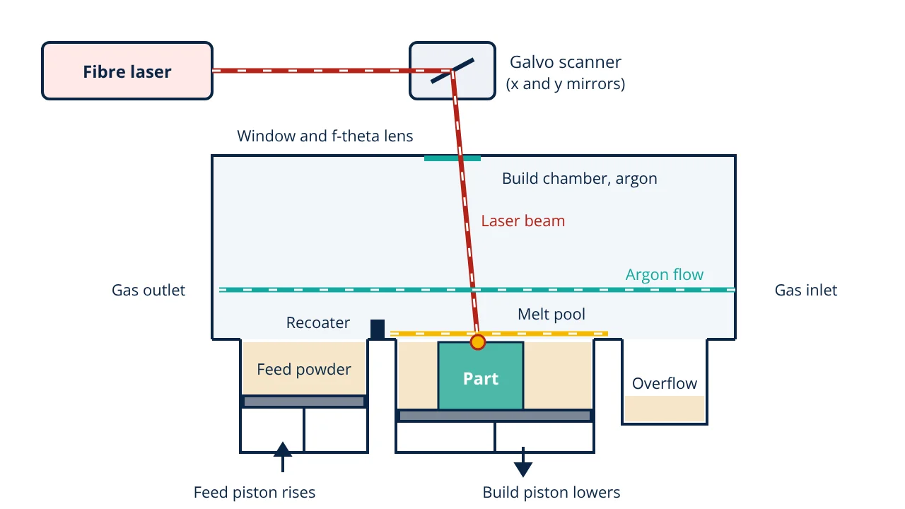
An L-PBF machine has four main systems: a high power fibre laser, a galvanometer scanner with two fast mirrors and an f-theta lens, a powder handling system (feed supply, recoater blade or roller, build piston and overflow), and a sealed chamber filled with argon or nitrogen. The process repeats the same cycle for every layer:
- Prepare the build. The CAD model is oriented, given support structures and sliced into layers, typically 20 to 100 µm thick. A metal build plate is fixed to the build piston and the chamber is purged with inert gas to a very low oxygen level.
- Spread a layer. The feed piston rises slightly and the recoater sweeps a thin, even layer of powder across the build area. Surplus powder falls into the overflow.
- Scan the layer. The galvo mirrors move the focused laser spot along the contour and hatch lines of the cross section. Each track melts the powder and partly remelts the layer below, so the new material fuses metallurgically with the part.
- Remove by-products. A steady laminar gas flow across the bed carries away metal vapour, condensate and spatter so they do not absorb the beam or fall onto the part.
- Lower and repeat. The build piston drops by one layer thickness and the cycle repeats until the part is complete. The part is then cooled, unpacked from the powder cake and the unused powder is sieved for reuse.
Electron beam powder bed fusion (EBM)
EB-PBF uses an electron beam steered by electromagnetic coils instead of mirrors, so it can deflect very quickly. Because electrons scatter in gas, the chamber runs under vacuum. Before melting, each layer is preheated by a defocused beam, which lightly sinters the powder so it does not scatter from electrostatic charging. The whole build stays hot during printing.
| Feature | L-PBF (SLM, DMLS) | EB-PBF (EBM) |
|---|---|---|
| Energy source | Fibre laser | Electron beam |
| Atmosphere | Argon or nitrogen | Vacuum |
| Build temperature | Low to moderate plate heating | High preheat of each layer |
| Residual stress | High, stress relief needed | Low, because the bed stays hot |
| Resolution and surface | Finer layers and detail | Coarser powder, rougher surface |
| Materials | Steels, aluminium, titanium, nickel alloys, cobalt chrome | Conductive alloys, notably titanium and nickel alloys |
Supports and design rules
In metal PBF, supports anchor the part to the build plate, hold up overhangs and conduct heat away from them. ISO/ASTM 52911-1 gives L-PBF design guidance: downward facing surfaces at a shallow angle to the plate need support, self-supporting angles are commonly around 45° from horizontal, and holes, channels and thin walls have practical minimum sizes. Designers also add powder escape holes to hollow regions and choose an orientation that limits support volume on functional surfaces.
Post-processing after metal 3D printing
- Stress relief heat treatment: done while the part is still on the plate, to reduce residual stress before cutting so the part does not distort.
- Part removal: wire EDM or a band saw separates parts from the build plate.
- Support removal: supports are cut, broken off or machined away, which leaves witness marks.
- Hot isostatic pressing (HIP): high temperature and high pressure inert gas close internal pores, improving fatigue life for critical parts.
- Heat treatment and finishing: solution and ageing treatments, as in heat treatment of steel, then machining of critical faces, bead blasting or polishing.
- Inspection: CT scanning and other NDT methods check for internal defects.
Materials for powder bed fusion
Common alloys include stainless steels such as 316L and 17-4 PH, maraging tool steel, aluminium alloys such as AlSi10Mg, titanium alloy Ti-6Al-4V, nickel superalloys such as Inconel 625 and 718, and cobalt chrome. Powders are usually gas atomised and spherical so they flow and pack well. Rapid solidification gives a very fine microstructure, so as-built strength often equals or exceeds that of castings, but ductility and fatigue depend strongly on defects and post-processing.
Defects in metal 3D printing
DebRoy et al. relate most defects to the melt pool and the thermal cycles:
- Lack of fusion porosity: too little energy leaves irregular voids with unmelted powder between tracks or layers.
- Keyhole porosity: too much energy creates a deep vapour cavity that collapses and traps round pores.
- Gas porosity: gas trapped in the powder or picked up from the atmosphere forms small spherical pores.
- Residual stress and distortion: steep thermal gradients and repeated heating and cooling lock in stress, causing warping, cracking or detachment from supports.
- Balling, spatter and roughness: unstable melt tracks and partly fused particles on surfaces.
Pores act as crack starters and cut fatigue life, which is why parameter control and HIP matter.
Volumetric energy density
A widely used first indicator for choosing L-PBF parameters is the volumetric energy density:
where P is laser power (W), v scan speed (mm/s), h hatch spacing (mm) and t layer thickness (mm), giving E in J/mm³. Too low an E tends towards lack of fusion; too high an E tends towards keyholing. It is only a guide, because the same E can give different melt pools.
- Given
- An L-PBF build uses laser power 200 W, scan speed 1000 mm/s, hatch spacing 0.1 mm and layer thickness 0.03 mm. The part is 60 mm tall with an average scanned area of 400 mm² per layer. Recoating takes 8 s per layer.
- Find
- The volumetric energy density and an estimate of build time.
- Assumptions
- One part on the plate; scan time = area ÷ (v × h); contour scans, jumps and gas purging ignored.
- Solution
- E = 200 ÷ (1000 × 0.1 × 0.03) = 200 ÷ 3 = 66.7 J/mm³
Number of layers = 60 ÷ 0.03 = 2000
Scan time per layer = 400 ÷ (1000 × 0.1) = 4 s
Time per layer = 4 + 8 = 12 s
Build time = 2000 × 12 = 24 000 s = 6.7 h - Answer
- E ≈ 66.7 J/mm³ and a build time of about 6.7 hours
- Limitations
- Energy density does not capture melt pool physics, and real build times include contours, supports and multiple parts, so machine software gives better estimates.
Note that recoating takes twice the scan time here, which is why machines nest many parts on one plate.
Key formulas for metal 3D printing
| Quantity | Formula | Symbols and units |
|---|---|---|
| Volumetric energy density | E = P ÷ (v × h × t) | P in W, v in mm/s, h and t in mm, E in J/mm³ |
| Number of layers | N = H ÷ t | H = part height in mm, t = layer thickness in mm |
| Scan time per layer | t_scan = A ÷ (v × h) | A = scanned area in mm², t_scan in s |
| Build time | T = N × (t_scan + t_recoat) | t_recoat = recoating time per layer in s |
Metal 3D printing interview and viva questions
- What is the difference between L-PBF and EB-PBF? L-PBF melts powder with a fibre laser in an argon or nitrogen atmosphere, while EB-PBF uses an electron beam in vacuum with a hot preheated bed, giving lower residual stress but coarser detail.
- Why is inert gas used in L-PBF? It prevents oxidation of the hot metal, and its flow across the bed removes vapour and spatter that would otherwise disturb the beam and the part.
- What is the role of the recoater? It spreads a thin, uniform layer of powder from the feed supply over the build area before each layer is scanned.
- What causes lack of fusion and keyhole porosity? Lack of fusion comes from too little energy input, and keyhole porosity from too much, which creates an unstable vapour cavity that traps pores.
- Why is HIP applied to some printed parts? Hot isostatic pressing closes internal pores using high temperature and gas pressure, improving fatigue performance of critical parts.
Frequently asked questions
What is the difference between SLM and DMLS?
Both are trade names for laser powder bed fusion of metals. Early DMLS machines partly sintered powder, but modern SLM and DMLS systems fully melt it, so ISO/ASTM 52900 groups them as L-PBF and the names are now used interchangeably.
Why do metal 3D printed parts need supports when SLS polymer parts do not?
Loose metal powder cannot hold up an overhang or conduct heat away fast enough, and metal parts develop high residual stress. Supports anchor the part to the build plate, resist warping and carry heat from overhanging regions.
Is hot isostatic pressing always required?
No. Stress relief is almost always needed in L-PBF, but HIP is mainly used for fatigue critical parts such as aerospace and medical components, where closing internal porosity is worth the extra cost.
References
- ISO/ASTM 52900:2021, Additive manufacturing: General principles, Fundamentals and vocabulary
- ISO/ASTM 52911-1:2019, Additive manufacturing: Design, Part 1: Laser-based powder bed fusion of metals
- I. Gibson, D. Rosen, B. Stucker and M. Khorasani, Additive Manufacturing Technologies, 3rd ed., Springer, 2021
- T. DebRoy et al., Additive manufacturing of metallic components: Process, structure and properties, Progress in Materials Science 92 (2018) 112 to 224
Get one engineering email a week
New articles, worked examples and study notes every week. Free, no spam, unsubscribe any time.