CNC Turning vs Milling: Differences
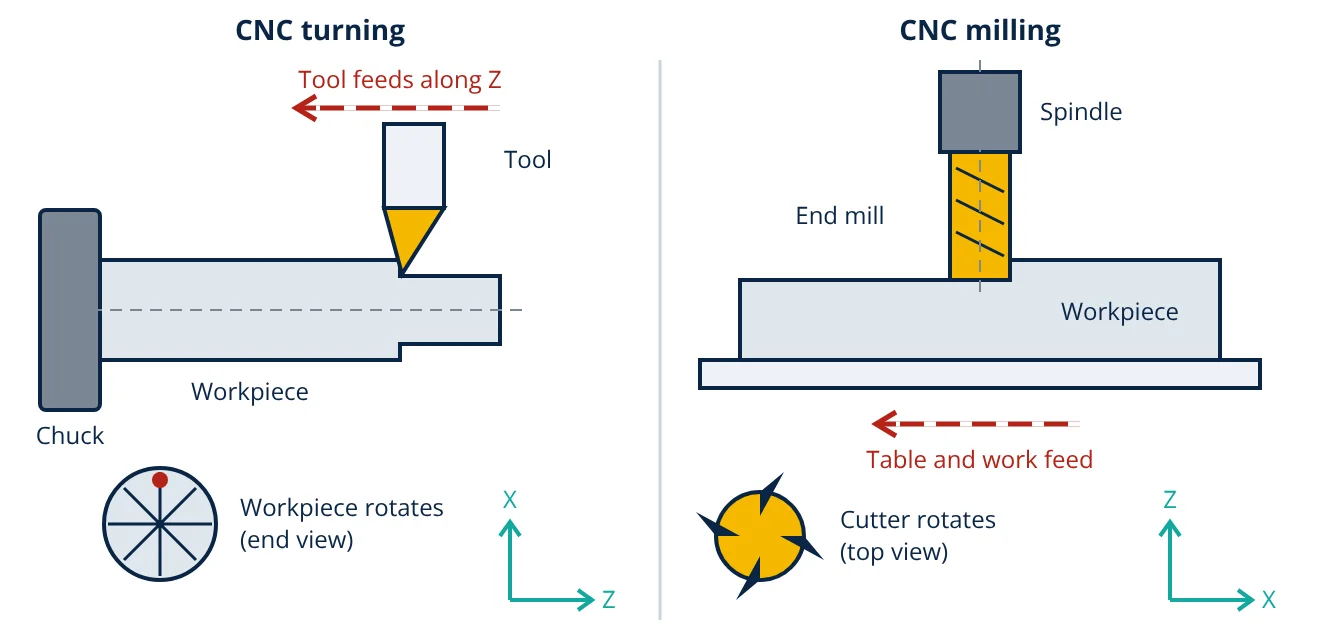
CNC turning vs milling is a comparison of two computer controlled machining processes. In turning, the workpiece rotates in a chuck while a stationary single point tool feeds along it, making round parts. In milling, a multi-tooth cutter rotates while the workpiece on the table feeds past it, making flat faces, slots and pockets.
The question of CNC turning vs milling comes up whenever a part is planned for machining. Both processes remove material as chips under program control, and both use the same controller logic, G-code and servo driven axes described in how a CNC machine works. The real difference is which element rotates and which element moves, and that single choice decides the part shapes each process makes well. Both belong to the material removal family in the classification of manufacturing processes.
How CNC turning works
Turning is done on a CNC lathe or turning centre. The workpiece is clamped in a chuck or collet and spun by the main spindle. A single point cutting tool, usually a carbide insert on a holder in a turret, is fed against the rotating work. Because every point of the cut surface passes the tool along a circle, turning naturally produces surfaces of revolution: cylinders, tapers, shoulders, grooves, threads and contoured profiles.
Under ISO 841:2001, the Z axis of a machine is parallel to the main spindle axis. On a lathe, Z therefore runs along the length of the workpiece, and X is radial, controlling the diameter. Moving the tool along Z produces length, and moving it along X changes diameter, so most turning programs are written in only two axes. Common operations, as listed by Groover and by Kalpakjian and Schmid, are straight turning, facing, taper turning, contour turning, grooving, parting off, boring, drilling on centre and threading.
How CNC milling works
Milling is done on a CNC milling machine or machining centre. A rotating cutter with several teeth, such as an end mill or face mill, is held in the spindle, and the workpiece is clamped to the table in a vise or fixture. The table (or in some designs the spindle head) moves along X, Y and Z so that the work feeds past the cutter. Each tooth takes a short, interrupted chip once per revolution, which is why milling is called an interrupted cutting process.
On a vertical machining centre the spindle is vertical, so Z is vertical, while X and Y move the table in the horizontal plane. With three linear axes under simultaneous control, milling makes flat faces, steps, slots, pockets, holes and three dimensional surfaces. Adding rotary axes gives four and five axis machining for complex parts. The two main types are peripheral milling, where the teeth on the cutter’s circumference cut, and face milling, where the cutter axis is perpendicular to the machined surface.
Motion in turning and milling
CNC turning vs milling comparison table
| Feature | CNC turning | CNC milling |
|---|---|---|
| Rotating element | Workpiece | Cutting tool |
| Feed motion | Tool moves along Z and X | Table or head moves along X, Y and Z |
| Cutting tool | Single point tool or insert | Multi-tooth cutter (end mill, face mill, drill) |
| Cut type | Continuous chip | Interrupted chip, one per tooth per revolution |
| Typical part shape | Shafts, pins, bushes, flanges, threaded parts | Plates, housings, brackets, moulds, pockets |
| Main axes (basic machine) | 2 (X and Z) | 3 (X, Y and Z) |
| Diameter in speed formula | Workpiece diameter | Cutter diameter |
| Feed specified as | mm per revolution of the work | mm per tooth, converted to mm/min |
| Typical workholding | Chuck, collet, centres | Vise, clamps, fixtures |
| Strong point | Roundness and concentricity | Flat faces and features on several sides |
Differences explained
Kinematics. In turning the primary cutting motion belongs to the work and the feed belongs to the tool. In milling the cutting motion belongs to the tool and the feed is usually applied to the work. This is the one difference from which all the others follow.
Speed and feed. In both cases the cutting speed is the surface speed at the cutting diameter, so the same equation gives spindle speed:
where N is in rpm, V_c is cutting speed in m/min and D is in mm. In turning D is the workpiece diameter; in milling it is the cutter diameter. Turning feed is given per revolution of the work (mm/rev). Milling feed is given per tooth and converted to a table feed rate:
Material removal rate. Following Groover and the Sandvik Coromant formulas, turning removes material at a rate equal to cutting speed times feed times depth of cut, while milling removes material at depth times width of cut times table feed:
Chip formation. A turning tool stays in the cut, so chips form continuously and long stringy chips need chip breaker geometry. A milling tooth enters and leaves the cut every revolution, so chip thickness varies and each tooth sees cyclic thermal and mechanical loading, as described by Kalpakjian and Schmid.
Programming. Both use the word address program format of ISO 6983-1:2009. Lathe programs often use diameter values for X and canned turning cycles, while milling programs work in three axes with cutter radius compensation and canned drilling cycles.
When to use which
Choose turning when the part is mainly round: shafts, axles, pins, bushes, pulleys, nozzles and threaded fittings. Choose milling when the part is mainly prismatic or has flat faces, slots, pockets or hole patterns off the axis. Many real parts need both, for example a shaft with a keyway. They are turned first and then milled, or made on a mill-turn centre with live tooling. For low volume plastic or complex internal shapes, additive processes covered in 3D printing technologies may compete with both. Workpiece material properties such as hardness, covered in mechanical properties of materials, set the cutting speed that both processes start from.
- Given
- Turning: steel bar of diameter 50 mm, cutting speed 200 m/min, feed 0.25 mm/rev, depth of cut 2 mm. Milling: 20 mm diameter end mill with 4 teeth, cutting speed 150 m/min, feed per tooth 0.05 mm, axial depth 5 mm, radial width 10 mm.
- Find
- Spindle speed for each process, the milling table feed rate, and the material removal rate for each.
- Assumptions
- Cutting data are taken as given for the tool and material; the machines can reach the speeds and supply the power; diameter change in turning is ignored for speed.
- Solution
- Turning: N = 1000 × 200 ÷ (π × 50) = 200 000 ÷ 157.08 = 1273 rpm
Q_turn = 200 × 0.25 × 2 = 100 cm³/min
Milling: N = 1000 × 150 ÷ (π × 20) = 150 000 ÷ 62.83 = 2387 rpm
v_f = 0.05 × 4 × 2387 = 477 mm/min
Q_mill = 5 × 10 × 477 ÷ 1000 = 23.9 cm³/min - Answer
- Turning: 1273 rpm and 100 cm³/min. Milling: 2387 rpm, 477 mm/min table feed and about 24 cm³/min.
- Limitations
- Real cutting data come from the tool supplier for the specific grade and material. Machine power, rigidity, tool overhang and surface finish requirements may force lower values.
Key formulas for CNC turning vs milling
| Quantity | Formula | Symbols and units |
|---|---|---|
| Cutting speed | V_c = π × D × N ÷ 1000 | V_c in m/min, D in mm, N in rpm |
| Spindle speed | N = 1000 × V_c ÷ (π × D) | D = work diameter (turning) or cutter diameter (milling), mm |
| Milling table feed | v_f = f_z × z × N | f_z = feed per tooth in mm, z = number of teeth, v_f in mm/min |
| Turning feed rate | v_f = f × N | f = feed in mm/rev, v_f in mm/min |
| MRR, turning | Q = V_c × f × a_p | a_p = depth of cut in mm, Q in cm³/min |
| MRR, milling | Q = a_p × a_e × v_f ÷ 1000 | a_e = radial width of cut in mm, Q in cm³/min |
CNC turning vs milling interview and viva questions
- What is the basic difference between turning and milling? In turning the workpiece rotates and a single point tool feeds along it. In milling the multi-tooth cutter rotates and the workpiece feeds past it.
- Which diameter is used to find spindle speed in each process? Turning uses the workpiece diameter at the cut, while milling uses the cutter diameter, both in N = 1000 V_c ÷ (π D).
- Why is milling called an interrupted cut? Each tooth engages the work for only part of a revolution, so it repeatedly enters and leaves the cut and produces separate chips.
- How is the Z axis defined on a lathe and on a vertical mill? Under ISO 841:2001 Z is parallel to the main spindle, so it runs along the work on a lathe and vertically on a vertical machining centre.
- How is milling feed rate calculated? Table feed equals feed per tooth times number of teeth times spindle speed, v_f = f_z × z × N, giving mm/min.
Frequently asked questions
Is CNC turning cheaper than CNC milling?
For round parts it usually is, because a lathe removes material continuously with a simple single point tool and short cycle times. For prismatic parts with pockets and flat faces, milling is the only practical choice, so cost depends mainly on part shape rather than on the process itself.
Can a CNC lathe do milling operations?
A turning centre with live (driven) tooling and a C axis that indexes or rotates the spindle under control can drill cross holes, mill flats and cut keyways. These mill-turn machines combine both processes so a part can be finished in one setup.
Which is more accurate, turning or milling?
Both reach tight tolerances on modern CNC machines. Turning generally holds roundness and concentricity better because all diameters are cut about the same spindle axis, while milling is better for flatness, positional accuracy of holes and features on several faces.
References
- S. Kalpakjian and S. R. Schmid, Manufacturing Engineering and Technology, 7th ed., Pearson
- M. P. Groover, Fundamentals of Modern Manufacturing: Materials, Processes, and Systems, 6th ed., Wiley
- ISO 841:2001, Industrial automation systems and integration: Numerical control of machines, Coordinate system and motion nomenclature
- ISO 6983-1:2009, Automation systems and integration: Numerical control of machines, Program format and definitions of address words
- Sandvik Coromant, Metalcutting Technical Guide: Turning, Milling and formulas and definitions
Get one engineering email a week
New articles, worked examples and study notes every week. Free, no spam, unsubscribe any time.