CNC Machine Working Principle and Main Parts
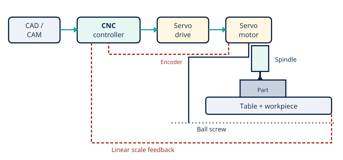
A CNC machine (computer numerical control) moves a cutting tool or workpiece automatically along programmed paths. A part program, usually G-code generated by CAM software, is loaded into the CNC controller. The controller interpolates the path and sends commands to servo drives and motors, which turn ball screws to move the machine axes along linear guides. Encoders and linear scales feed back position so the controller can correct errors in a closed loop. The spindle rotates the tool (milling) or the workpiece (turning) at programmed speed. Main types are CNC mills, lathes, routers, grinders, EDM, laser and plasma cutters.
CNC machines brought the accuracy and repeatability of computers to metal cutting. They produce parts within micrometres, run unattended for hours, and switch between jobs simply by loading a new program. They are the backbone of modern machining, from small job shops to aerospace and automotive production lines.
How a CNC machine works
- Design: the part is modelled in CAD.
- CAM programming: CAM software calculates tool paths for each operation, considering tools, cutting speeds, feeds and stock, and a post processor outputs G-code for the specific machine and controller.
- Setup: the operator fixes the workpiece in a vice or fixture, loads tools, measures tool lengths and sets work offsets that link the program’s origin to the part.
- Execution: the controller reads each block, plans motion with acceleration limits and look-ahead, and continuously sends position commands to the axis drives.
- Feedback and correction: encoders on motors, and often linear scales on axes, report actual positions; the servo loop corrects any difference thousands of times per second.
- Inspection: parts are checked with gauges, probes or a coordinate measuring machine.
Main parts of a CNC machine
- Machine structure (bed, column, saddle): cast iron, welded steel or polymer concrete, designed for stiffness and vibration damping.
- CNC controller: industrial computer with the HMI, program memory, motion planning (interpolation), PLC for machine logic, and drive interfaces. Common brands include Fanuc, Siemens, Heidenhain, Mitsubishi and Haas.
- Axis drives and motors: AC servo motors with encoders give fast, precise motion; linear motors are used in high speed machines. See servo vs stepper motor.
- Ball screws and linear guides: convert rotation into smooth, low friction linear motion with minimal backlash.
- Spindle: a precision motorised shaft holding the tool (mill) or workpiece (lathe), with speeds from a few hundred to over 30 000 rpm.
- Automatic tool changer (ATC): a magazine or turret that swaps tools in seconds.
- Workholding: vices, chucks, fixtures, pallets and rotary tables.
- Coolant and chip management: pumps, nozzles, chip conveyors and filtration.
- Probing and measurement: touch probes for setting work offsets and checking parts, tool setters for length and wear.
- Enclosure and safety interlocks.
Axes and coordinate system
Axes follow ISO 841: Z is along the spindle axis, X is usually the longest horizontal travel, and Y completes a right handed system. Rotary axes A, B and C rotate about X, Y and Z. A 3-axis mill moves X, Y, Z; 4-axis adds one rotary axis; 5-axis adds two, allowing complex surfaces in one setup.
G-code basics
A short milling program fragment:
G21 G90 G17metric units, absolute coordinates, XY planeT1 M06load tool 1S2000 M03spindle 2000 rpm clockwiseG00 X0 Y0 Z5rapid move above the startG01 Z-2 F150feed down 2 mm at 150 mm/minG01 X50 F400cut a straight lineG02 X60 Y10 R10cut a clockwise arcM05 M30spindle stop, program end
Cutting speed and feed
Spindle speed comes from the recommended cutting speed V_c for the tool and material:
where N is in rpm, V_c in m/min and D the tool (or workpiece) diameter in mm. Feed rate for milling is:
where f_z is feed per tooth and z the number of teeth.
- Given
- A 12 mm, 4-flute carbide end mill cuts aluminium alloy with recommended cutting speed 300 m/min and feed per tooth 0.05 mm.
- Find
- Spindle speed and feed rate.
- Assumptions
- Machine can reach the calculated speed; rigid setup.
- Solution
- N = 1000 × 300 ÷ (π × 12) = 300 000 ÷ 37.70 = 7958 rpm
V_f = 0.05 × 4 × 7958 = 1592 mm/min - Answer
- About 7960 rpm and 1590 mm/min feed
- Limitations
- Depth of cut, machine power, rigidity and chip evacuation may require lower values; tool supplier data should be checked.
Types of CNC machines
- CNC milling machines and machining centres (vertical and horizontal), the most common.
- CNC lathes and turning centres, often with live tooling and a sub spindle (mill-turn).
- CNC routers for wood, plastics and composites.
- CNC grinders for precision finishing.
- Wire and sinker EDM for hard materials and intricate shapes.
- Laser, plasma and waterjet cutters for sheet and plate.
- CNC press brakes for bending.
Advantages and limitations of a CNC machine
Advantages: high accuracy and repeatability, complex shapes, quick changeover between jobs, reduced reliance on operator skill, unattended running, and digital integration with CAD/CAM and production systems.
Limitations: high capital cost, need for skilled programmers and maintenance, and machining wastes material as chips. CNC machining remains a core subtractive process among the manufacturing processes, increasingly combined with 3D printing for hybrid production.
Programming methods
Programs can be written by hand for simple parts, created with conversational programming at the control, where the operator fills in prompts for pockets, holes and contours, or generated by CAM software for complex 3D shapes. Simulation in CAM or on the control checks for collisions and gouges before cutting. Canned cycles such as G81 for drilling and G83 for peck drilling shorten programs for repeated operations, and cutter radius compensation (G41 and G42) lets programs follow part geometry while the control offsets for tool size.
Maintenance and accuracy
Accuracy depends on regular maintenance: lubrication of guides and screws, spindle bearing checks, backlash compensation, ballbar tests for circularity and laser calibration of axis positioning. Thermal growth of the spindle and structure is a major error source, so warm-up cycles and thermal compensation are used. Planned types of maintenance such as preventive and predictive programmes keep machines productive.
Frequently asked questions
What does CNC stand for?
CNC stands for Computer Numerical Control. Earlier NC machines read instructions from punched tape; CNC machines use a built-in computer that stores programs, interpolates tool paths, controls motors in real time and allows editing at the machine.
What is the difference between G-code and M-code?
G-codes are preparatory commands that define motion and geometry, such as G00 rapid positioning, G01 linear feed, G02 and G03 circular arcs, and G90 absolute positioning. M-codes are miscellaneous machine functions, such as M03 spindle on clockwise, M05 spindle stop, M08 coolant on and M30 end of program.
What does 5-axis mean in CNC machining?
A 5-axis machine moves the tool relative to the part along three linear axes (X, Y, Z) plus two rotary axes, such as A and C or B and C. This lets the tool approach complex surfaces from many angles in one setup, which is essential for turbine blades, impellers, moulds and aerospace parts.
References
- ISO 6983-1:2009, Automation systems and integration: Numerical control of machines, Program format and definitions of address words
- ISO 841:2001, Industrial automation systems and integration: Numerical control of machines, Coordinate system and motion nomenclature
- P. Smid, CNC Programming Handbook, 3rd ed., Industrial Press
- Y. Altintas, Manufacturing Automation: Metal Cutting Mechanics, Machine Tool Vibrations, and CNC Design, 2nd ed., Cambridge University Press
Get one engineering email a week
New articles, worked examples and study notes every week. Free, no spam, unsubscribe any time.