Bolted vs Welded Connections in Steel Structures
Bolted vs welded connections is the choice between joining steel members with bolts, which carry force by shear and bearing or by clamped friction, and with welds, which fuse the parts so force passes through the weld throat. Bolting is fast, easy to inspect and removable; welding is compact, rigid and continuous but needs skilled welders.
Every steel frame, truss and bridge is only as good as its joints. The comparison of bolted vs welded connections comes up on every project, because the connection type affects design strength, fabrication cost, erection speed, inspection and long term behaviour under fatigue. This article explains how each type works, the main design checks in IS 800:2007, and how engineers decide which to use.
How bolted vs welded connections transfer load
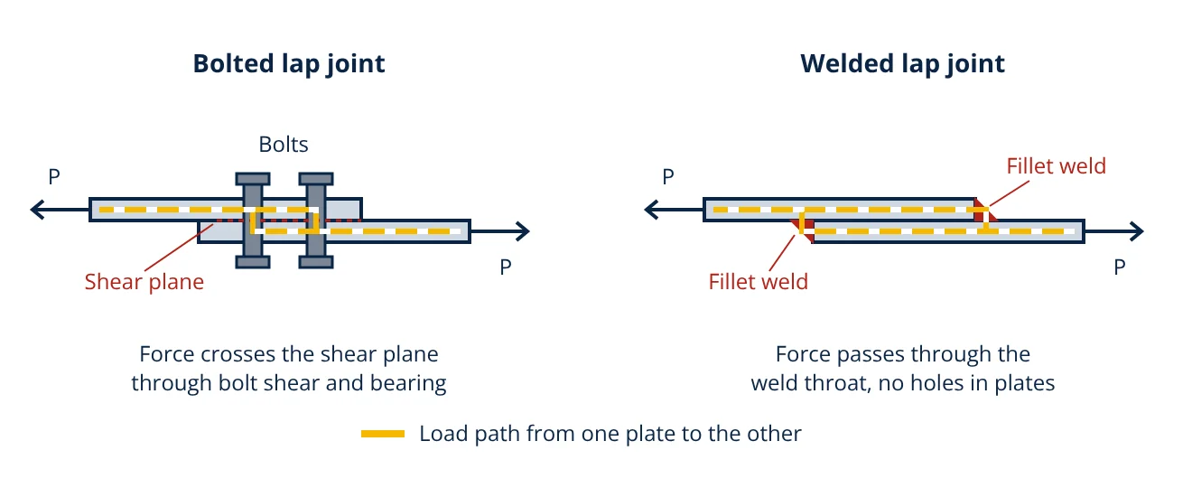
In a bolted joint, the tension in one plate has to cross into the other plate through the bolts. In an ordinary bearing type joint the plates slip slightly until the hole walls bear on the bolt shank. The bolt is then sheared across the plane between the plates while the plates bear against it. In a friction grip joint the bolts are tightened to a high pretension so the plates are clamped together and the load passes by friction at the faying surfaces.
In a welded joint, the plates are fused by deposited weld metal. Force flows through the weld, and for a fillet weld the critical section is the throat, the smallest dimension across the weld. There are no holes, so the full plate area is available, and the joint behaves almost as one continuous piece of steel.
Bolted connections
Structural bolts are classified by property class. In ISO 898-1, class 4.6 bolts have a nominal ultimate strength of 400 MPa and yield of 240 MPa, while high strength class 8.8 and 10.9 bolts have nominal ultimate strengths of 800 and 1000 MPa. IS 800 covers two design approaches:
- Bearing type bolts: checked for shear, bearing on the plate and tension. Holes are slightly larger than the bolt, for example 22 mm for an M20 bolt in standard clearance holes.
- High strength friction grip (HSFG) bolts: pretensioned so the joint does not slip. Design slip resistance depends on the slip factor of the contact surfaces, the number of interfaces and the bolt proof load.
Detailing rules in IS 800 include a minimum pitch of 2.5 times the bolt diameter and minimum edge distances related to the hole diameter. Bolts reduce the net area of the member, so tension members need a net section check, and groups of holes need a block shear check.
Welded connections
The two main structural welds are fillet welds, laid in the corner between two surfaces, and butt (groove) welds, which join parts edge to edge through their thickness. Most building connections use fillet welds because they need no edge preparation. Welding processes such as shielded metal arc, flux cored and submerged arc welding are described in types of welding processes.
For a fillet weld with a 90° fusion angle, IS 800 takes the effective throat as 0.7 times the weld size. The design strength uses the lower ultimate strength of the weld metal and the parent metal, with a partial safety factor of 1.25 for shop welds and 1.50 for field welds. The effective length of a fillet weld is its overall length minus twice the weld size, to allow for craters at the ends. IS 816 and AWS D1.1 set out procedures, welder qualification and workmanship.
Welding introduces heat, so welded parts can carry residual stresses and distortion. Thick plates loaded through their thickness can suffer lamellar tearing, and weld toes are stress concentrations that govern fatigue life.
Bolted vs welded connections: comparison table
| Feature | Bolted connection | Welded connection |
|---|---|---|
| Load transfer | Bolt shear and bearing, or friction (HSFG) | Through weld throat or full penetration weld |
| Effect on member | Holes reduce net area | Full section used, no holes |
| Stiffness | Some slip in bearing type joints | Rigid, no slip |
| Site work | Fast, no hot work, weather tolerant | Needs power, shelter, preheat for thick parts, fire watch |
| Skill needed | Moderate; correct tightening is key | Qualified welders and procedures |
| Inspection | Visual and torque or tension checks | Visual plus NDT such as UT, MT or RT |
| Dismantling | Easy to remove or replace | Cutting needed |
| Appearance and size | Bulkier splice plates and cleats | Compact, clean lines |
| Fatigue | HSFG joints perform well; bearing joints can loosen | Weld toe details often govern |
| Partial safety factor in IS 800 | 1.25 for bolts | 1.25 shop, 1.50 field |
When to use which
Common practice in steel construction combines both. Members are welded in the shop, where conditions are controlled, and bolted on site, where speed and simple inspection matter. Typical choices:
- Bolting suits site splices, beam to column cleats, structures that may be extended or dismantled, and remote sites with limited welding support.
- HSFG bolting suits joints under load reversal, vibration or where slip would cause problems, such as crane girders and bridge splices.
- Welding suits built up plate girders, stiffeners, base plates, tubular trusses of hollow sections and moment connections needing high rigidity.
For bridges and other structures under repeated load, see types of bridges; detail categories in IS 800 Section 13 and EN 1993-1-9 rate both bolted and welded details for fatigue.
Design checks to IS 800
IS 800 uses limit state design, so factored loads are compared with design strengths reduced by partial safety factors. For a bearing type bolt, the design shear strength is
and the design bearing strength is
where k_b is the smallest of e/3d₀, p/3d₀ − 0.25, f_ub/f_u and 1.0. For a fillet weld, the design strength per unit length is
- Given
- A factored tension of 200 kN is carried by a lap joint between 10 mm plates of E250 steel (f_u = 410 MPa). Option A: M20 class 4.6 bolts in single shear with the shear plane through the threads (A_nb = 245 mm², d₀ = 22 mm, end distance 40 mm, pitch 60 mm). Option B: 6 mm shop fillet welds, two side welds.
- Find
- The number of bolts for option A and the length of each side weld for option B.
- Assumptions
- IS 800:2007, γ_mb = 1.25, γ_mw = 1.25, weld metal strength not less than 410 MPa, load shared equally, member and block shear checked separately.
- Solution
- Bolt shear: V_dsb = 400 × 245 ÷ (1.732 × 1.25) = 45.3 kN
k_b = min(40/66, 60/66 − 0.25, 400/410, 1) = 0.606
Bearing: V_dpb = 2.5 × 0.606 × 20 × 10 × 410 ÷ 1.25 = 99.4 kN, so shear governs
Bolts: 200 ÷ 45.3 = 4.42, use 5
Weld: f_wd = 410 ÷ (1.732 × 1.25) = 189.4 MPa, t_e = 0.7 × 6 = 4.2 mm
q = 4.2 × 189.4 = 795 N/mm
Effective length = 200000 ÷ 795 = 251 mm, so 126 mm per side
Overall length per side = 126 + 2 × 6 = 138 mm, use 140 mm - Answer
- Option A: 5 bolts M20 class 4.6. Option B: two 6 mm fillet welds, each 140 mm long.
- Limitations
- Net section, block shear, long joint reduction and minimum weld size rules also apply. A field weld (γ_mw = 1.50) would need about 302 mm of effective length in total.
Key formulas for bolted vs welded connections
| Quantity | Formula | Symbols and units |
|---|---|---|
| Bolt design shear strength | V_dsb = f_ub (n_n A_nb + n_s A_sb) ÷ (√3 γ_mb) | f_ub in MPa, A_nb and A_sb = net and shank areas in mm², n_n and n_s = shear planes through threads and shank |
| Bolt design bearing strength | V_dpb = 2.5 k_b d t f_u ÷ γ_mb | d = bolt diameter, t = plate thickness in mm, f_u in MPa |
| Bearing factor | k_b = min(e/3d₀, p/3d₀ − 0.25, f_ub/f_u, 1.0) | e = end distance, p = pitch, d₀ = hole diameter in mm |
| Fillet weld throat | t_e = 0.7 s | s = weld size in mm, 90° fusion faces |
| Fillet weld strength per length | q = t_e f_u ÷ (√3 γ_mw) | q in N/mm, γ_mw = 1.25 shop, 1.50 field |
| Effective weld length | L_eff = L − 2s | L = overall weld length in mm |
Inspection and quality
Bolted joints are inspected visually for correct bolt grade, washers, thread projection and hole quality. For HSFG bolts, the specified pretension is confirmed by torque control, turn of nut or direct tension indicators. Welded joints need a written welding procedure, qualified welders and inspection for size, profile, cracks, porosity and undercut. Important welds are tested with non-destructive testing methods such as ultrasonic, magnetic particle or radiographic testing. Inspection effort is part of the real cost of each option and is often the deciding factor on site.
Bolted vs welded connections interview and viva questions
- What are the two ways a bolted joint can transfer shear? By bearing, where the bolt shank is sheared and bears on the hole walls, or by friction, where pretensioned HSFG bolts clamp the plates so friction carries the load without slip.
- What is the throat of a fillet weld? It is the smallest distance across the weld section, taken as 0.7 times the weld size for a fillet weld with 90° fusion faces in IS 800, and it is the section used to calculate weld strength.
- Why does IS 800 use a higher partial safety factor for field welds? Site welding has less control over position, weather and inspection than shop welding, so IS 800 uses 1.50 for field welds against 1.25 for shop welds.
- What is block shear? It is a failure mode of a bolted end connection where a block of plate tears out along a combination of shear and tension planes through the bolt holes.
- Why are welded details often critical in fatigue? The weld toe is a sharp change in geometry with residual stresses and small defects, so fatigue cracks start there under repeated loading.
Frequently asked questions
Are welded connections stronger than bolted connections?
Not by definition. Either type can be designed to carry the required force. A welded joint uses the full plate without holes, so it is often more compact and stiffer, while a bolted joint reaches the same design strength with enough bolts of a suitable grade. The choice usually depends on site conditions, inspection, fatigue and cost rather than raw strength.
Why are steel members often welded in the shop and bolted on site?
Shop welding is done in controlled conditions with positioners, qualified welders and easy inspection, which is why IS 800 allows a lower partial safety factor for shop welds (1.25) than for field welds (1.50). Bolting on site is fast, needs no hot work, is less weather dependent and is simple to inspect.
What is the difference between bearing type and friction grip bolts?
In a bearing type joint the plates slip into contact with the bolt and the load passes by bolt shear and bearing on the hole. In a friction grip (slip critical) joint, high strength bolts are pretensioned so the clamped plates carry the load by friction and do not slip at working load. Friction grip joints are used where slip or load reversal must be avoided.
References
- IS 800:2007 General Construction in Steel, Code of Practice, Bureau of Indian Standards
- IS 816:1969 Code of Practice for Use of Metal Arc Welding for General Construction in Mild Steel, Bureau of Indian Standards
- EN 1993-1-8:2005 Eurocode 3: Design of steel structures, Part 1-8: Design of joints, CEN
- ANSI/AISC 360-22 Specification for Structural Steel Buildings, American Institute of Steel Construction
- AWS D1.1/D1.1M:2020 Structural Welding Code, Steel, American Welding Society
- ISO 898-1:2013 Mechanical properties of fasteners made of carbon steel and alloy steel, Part 1: Bolts, screws and studs
- N. Subramanian, Design of Steel Structures, Oxford University Press
Get one engineering email a week
New articles, worked examples and study notes every week. Free, no spam, unsubscribe any time.