Rock Bolting and Ground Support Methods Explained
Rock bolting is the installation of steel bars or tubes into drilled holes around an underground opening to reinforce the rock mass. Bolts suspend loose layers from stable rock, clamp thin beds into a stiffer beam and key blocks together. Mesh, shotcrete, straps and cable bolts complete the ground support system.
Rock bolting is the most widely used method of ground support in underground mines and tunnels. When an opening is excavated, the rock around it loses confinement, joints open and blocks can loosen and fall. Rock bolts, together with surface support such as mesh and shotcrete, help the rock carry its own load so that the opening stays safe for people and equipment.
Choosing the right support starts with understanding the rock. Rating systems described in rock mass classification are the usual first step, followed by mapping of joints and wedges in the opening.
How rock bolting works
Rock bolts do not hold a mine up like columns. They work with the rock in three main ways, described in Hoek, Kaiser and Bawden and in Brady and Brown.
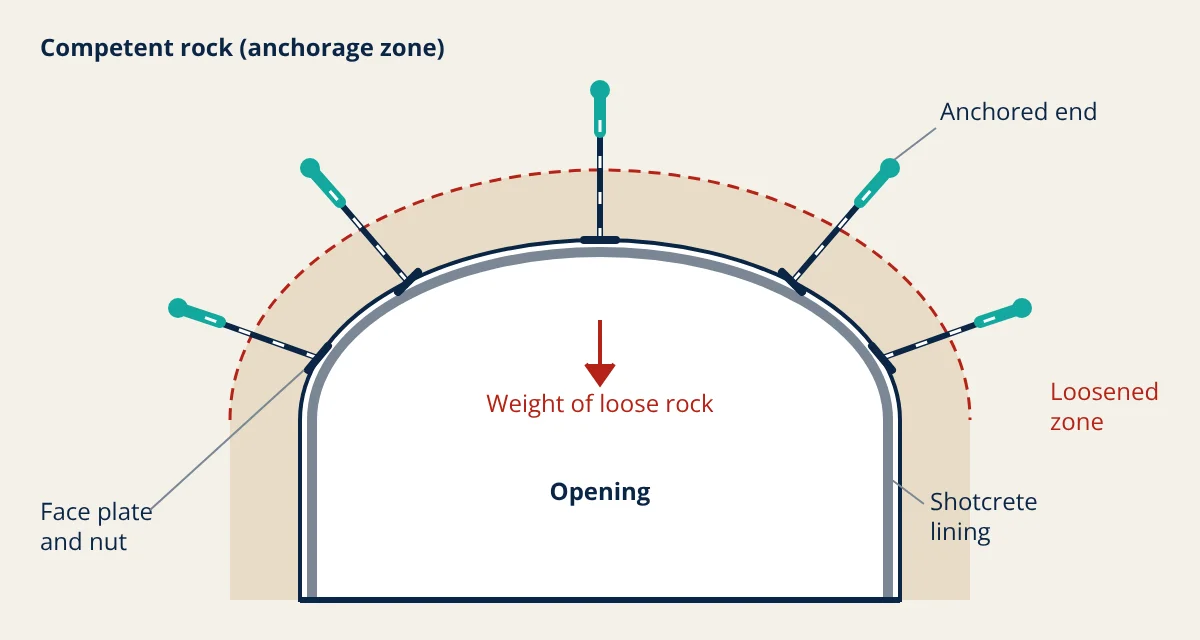
- Suspension: a weak or loosened layer is hung from stronger rock above. Each bolt carries the dead weight of the rock in its tributary area and transfers it to the anchorage.
- Beam building: in thinly bedded roofs, bolts clamp several thin layers together so they act as one thicker beam. A thicker beam is much stiffer and stronger in bending than the separate layers sliding past each other.
- Keying and arching: in jointed rock, bolts hold blocks together and keep the interlock between them, so the rock around the opening forms a self supporting arch in compression.
The diagram shows the suspension idea in a typical arched roof. The loosened zone around the opening is held by a pattern of bolts that reach well into stable rock.
Types of rock bolts
Bolts are grouped by how they grip the rock along the hole. Hoek, Kaiser and Bawden describe each type and its typical use.
Mechanically anchored bolts
An expansion shell at the end of the bolt is wedged against the hole wall when the bolt is turned, and the bolt is then tensioned against a face plate. These are quick to install and give immediate active support, but the anchor can slip in soft rock and the ungrouted steel is exposed to corrosion. They are often grouted later for long term use.
Fully grouted rebar bolts
A deformed steel bar is bonded along its whole length with resin cartridges or cement grout. Resin sets in minutes and allows early tensioning; cement grout is cheaper but needs curing time. Full bonding makes the bolt stiff and resistant to corrosion, and it is the standard choice for permanent openings.
Friction bolts
Friction bolts grip the hole wall over their full length by radial pressure. Split set bolts are slotted steel tubes driven into a slightly smaller hole. Inflatable bolts (such as Swellex) are folded tubes expanded by high pressure water. They install fast and tolerate rock movement, which suits short term mining support, but their capacity depends on hole diameter and they are prone to corrosion.
Cable bolts
Cable bolts are steel strands, usually grouted with cement, installed in long holes. They reach much deeper than rebar bolts and are used for wide spans, intersections, stope hanging walls and crown pillars.
| Bolt type | Grip mechanism | Typical use |
|---|---|---|
| Mechanically anchored | Expansion shell at end | Quick active support, temporary roofs |
| Resin or cement grouted rebar | Bond along full length | Permanent openings, development drives |
| Split set or inflatable | Friction along full length | Fast short term mining support |
| Cable bolt | Grouted strand | Long spans, stopes, intersections |
Surface support and other ground support methods
Bolts reinforce the rock in depth, but small pieces can still fall between bolt plates. Surface support holds this rock:
- Welded wire mesh or chain link mesh: pinned by the bolt plates, it catches small pieces and transfers their load to the bolts.
- Shotcrete: sprayed concrete, often fibre reinforced, applied soon after excavation. It seals the surface, prevents ravelling and supports wedges between bolts.
- Straps and lacing: steel straps link bolt heads across weak bands or around corners.
- Steel sets and lattice girders: used in very poor ground where bolts cannot find good anchorage, often with shotcrete.
Ground support is a system. Bolts, mesh and shotcrete are only as strong as their connections, so plates, nuts and mesh overlaps matter. Support should also follow controlled drilling and blasting, because poor blasting damages the rock and increases the load on support.
Design rules for rock bolting
Dead weight suspension
For a loose layer of known thickness, the load on each bolt equals the weight of rock in its tributary area:
where γ is the unit weight of rock, h the thickness of the loose layer and s1, s2 the bolt spacings along and across the opening. The factor of safety is the bolt capacity divided by W.
Empirical rules from the Q-system
Barton, Lien and Lunde related the Q value to support needs. The maximum span that can stand without support is:
and a guide for roof bolt length in metres is:
where B is the span or height in metres and ESR is the excavation support ratio, which reflects how critical the opening is. The NGI handbook gives ESR values of about 1.6 for permanent mine openings and lower values for road tunnels and caverns where safety demands are higher.
Key formulas for rock bolting
| Quantity | Formula | Symbols and units |
|---|---|---|
| Load per bolt (suspension) | W = γ h s1 s2 | γ in kN/m³, h, s1, s2 in m, W in kN |
| Factor of safety | FS = P_bolt ÷ W | P_bolt = bolt capacity in kN |
| Maximum unsupported span | Span_max = 2 ESR Q^0.4 | Span in m, Q dimensionless, ESR from Q-system tables |
| Roof bolt length | L = 2 + 0.15 B ÷ ESR | L and B in m |
- Given
- A permanent mine drive 5 m wide in rock with Q = 2, so ESR = 1.6. Mapping shows a loosened roof layer 1.2 m thick with unit weight 26 kN/m³. Proposed pattern 1.2 m by 1.2 m. Bolt capacity 120 kN, as stated by the supplier.
- Find
- Whether support is needed, the guide bolt length, the load per bolt and the factor of safety.
- Assumptions
- The loose layer acts as dead weight only; bolts are fully anchored beyond the loose zone; no load from high stress or blasting damage.
- Solution
- Span_max = 2 × 1.6 × 2^0.4 = 4.22 m, less than 5 m, so support is needed
L = 2 + 0.15 × 5 ÷ 1.6 = 2.47 m, and the bolt must also pass the 1.2 m loose layer with enough anchorage length
W = 26 × 1.2 × 1.2 × 1.2 = 44.9 kN
FS = 120 ÷ 44.9 = 2.67 - Answer
- Support is required; bolts about 2.5 m long on a 1.2 m by 1.2 m pattern give a factor of safety of about 2.7 against dead weight
- Limitations
- Dead weight design ignores stress driven failure, wedge geometry and dynamic loads. Wedge analysis and site experience should confirm the design.
Installation, testing and monitoring
Good bolting depends on good installation. Holes should be drilled to the correct diameter and length, cleaned, and filled with the right amount of resin or grout. Plates must sit flat against the rock. Pull tests check anchorage on a sample of bolts, and ASTM F432 sets material and dimension requirements for roof and rock bolts and their accessories.
Mines also monitor support performance with extensometers, convergence measurements and regular visual inspection, as part of managing mine hazards such as falls of ground. Where conditions change, the support pattern is updated. Support needs also differ between methods, as explained in surface vs underground mining.
Rock bolting interview and viva questions
- What are the three main ways rock bolts support rock? Suspension of loose layers from stable rock, beam building by clamping thin beds together, and keying blocks so the rock forms a self supporting arch.
- Why are fully grouted rebar bolts preferred for permanent openings? They are bonded along their whole length, which makes them stiff and protects the steel from corrosion.
- What is the advantage of friction bolts such as split sets? They install quickly and tolerate rock movement, which suits short term mining support, though they are prone to corrosion.
- How is the load on a bolt found in dead weight design? Multiply the unit weight of rock by the loose layer thickness and the two bolt spacings, W = γ h s1 s2.
- Why is mesh or shotcrete used with rock bolts? Bolts reinforce the rock in depth, but small pieces between plates can fall; surface support holds them and transfers their load to the bolts.
Frequently asked questions
What is the difference between active and passive rock bolts?
An active bolt is tensioned at installation, so it applies a compressive load to the rock straight away, as with a tensioned mechanically anchored bolt. A passive bolt, such as an untensioned fully grouted rebar or a friction bolt, carries load only when the rock starts to move and stretches the bolt.
Why are rock bolts installed in a pattern rather than one by one?
A regular pattern makes the bolted rock act as a reinforced unit and makes sure every potentially loose block is crossed by at least one bolt. Individual spot bolts are still used to pin specific wedges identified by mapping, but pattern bolting is the normal approach for roofs and walls of mine openings.
Can rock bolts be used without mesh or shotcrete?
In good, massive rock with widely spaced joints, bolts alone may be enough. In jointed or broken rock, small pieces can ravel out between the bolt plates, so surface support such as welded mesh or shotcrete is added to hold the rock between bolts and transfer its load back to the bolts.
References
- E. Hoek, P. K. Kaiser and W. F. Bawden, Support of Underground Excavations in Hard Rock, A. A. Balkema, 1995
- E. Hoek, Practical Rock Engineering, RocScience, 2007
- B. H. G. Brady and E. T. Brown, Rock Mechanics for Underground Mining, 3rd ed., Springer, 2004
- N. Barton, R. Lien and J. Lunde, Engineering classification of rock masses for the design of tunnel support, Rock Mechanics, 6, 189-236, 1974
- NGI, Using the Q-system: Rock mass classification and support design, Norwegian Geotechnical Institute, 2015
- ASTM F432, Standard Specification for Roof and Rock Bolts and Accessories, ASTM International
Get one engineering email a week
New articles, worked examples and study notes every week. Free, no spam, unsubscribe any time.