Drilling and Blasting in Mining: Basics
Drilling and blasting breaks hard rock in mines and quarries. Holes are drilled in a planned pattern, charged with explosives, stemmed with crushed rock to confine the energy, and initiated in a timed sequence. Key design parameters are hole diameter, burden (distance to the free face), spacing between holes, bench height, subdrill, stemming length and delay timing. The powder factor, kilograms of explosive per cubic metre of rock, summarises the design. Good blasting gives the right fragment size for loading and crushing while controlling vibration, flyrock and wall damage.
Most ore and waste rock in hard rock mines is broken by explosives. The quality of a blast affects every downstream step: how fast shovels can dig, how much fuel trucks use, how much energy the crusher and mill need, and how stable the pit walls remain. Drilling and blasting is therefore one of the most important cost drivers in mining.
How explosives break rock
When an explosive detonates, it releases very high pressure gas almost instantly. Two effects break the rock:
- Shock (stress) wave: travels outward from the hole at several km/s, crushing rock near the hole and creating radial cracks. When it reflects from a free face as a tension wave, it causes spalling, because rock is much weaker in tension than compression.
- Gas pressure: expanding gases enter and extend the cracks and push the broken rock mass forward towards the free face.
A free face, an open surface such as a bench face, is essential: rock must have room to move.
Bench blast geometry
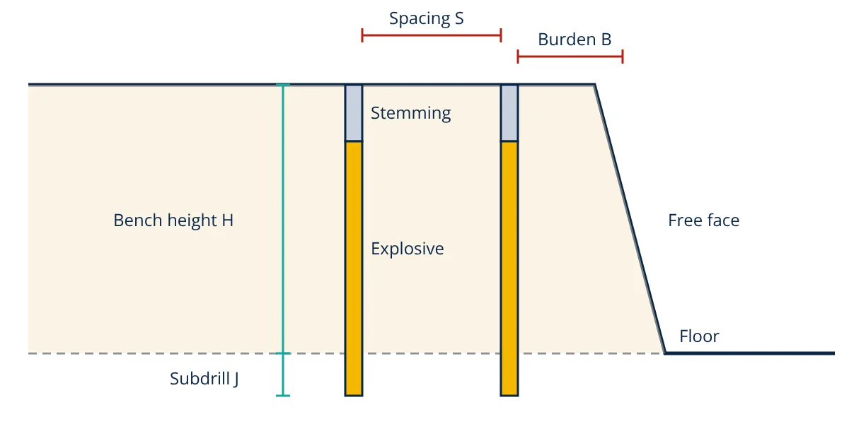
- Hole diameter (d): typically 89 to 311 mm in surface mines, smaller underground. Larger holes cut drilling cost but give coarser fragmentation.
- Burden (B): distance from a hole to the nearest free face, often about 25 to 40 times the hole diameter.
- Spacing (S): distance between holes in a row, typically 1.0 to 1.5 times the burden. Staggered patterns spread energy more evenly.
- Bench height (H): set by loading equipment and ore selectivity; ideally at least about 2.5 to 4 times the burden for good breakage.
- Subdrill (J): extra depth below floor level, about 0.3 times the burden, to break the toe and leave a flat floor.
- Stemming (T): inert material at the top of the hole, about 0.7 to 1.0 times the burden, that confines gases and controls flyrock and air blast. Crushed angular rock works better than drill cuttings.
Explosives and initiation
- ANFO: ammonium nitrate and fuel oil, cheap and widely used in dry holes.
- Emulsions: water resistant, higher density and energy; pumped from bulk trucks into wet holes.
- Heavy ANFO blends: mixtures of emulsion and ANFO for flexibility.
- Boosters and primers: small high strength charges, often cast pentolite, that reliably initiate the main charge.
- Initiation systems: detonating cord, non-electric shock tube detonators, electric detonators and electronic detonators, which offer precise, programmable delays of 1 ms accuracy and are increasingly standard.
Timing typically gives about 3 to 8 ms per metre of burden between holes in a row and longer delays between rows, so each row has time to move before the next fires.
Powder factor
- Given
- A bench of 10 m height in medium strength rock, holes of 165 mm diameter, burden 5 m, spacing 6 m, subdrill 1.5 m, stemming 4 m. Bulk emulsion density 1.15 g/cm³.
- Find
- Hole depth, charge length, explosive mass per hole, rock volume per hole and powder factor.
- Assumptions
- Vertical holes; the hole is fully charged below the stemming.
- Solution
- Hole depth = H + J = 10 + 1.5 = 11.5 m
Charge length = 11.5 − 4 = 7.5 m
Linear charge = π × 0.165² ÷ 4 × 1150 = 0.02138 × 1150 = 24.6 kg/m
Charge per hole = 24.6 × 7.5 = 184 kg
Rock volume = 5 × 6 × 10 = 300 m³
PF = 184 ÷ 300 = 0.61 kg/m³ - Answer
- About 184 kg of emulsion per 11.5 m hole, breaking 300 m³ at a powder factor of 0.61 kg/m³
- Limitations
- Optimum values depend on rock properties, structure and desired fragmentation; trial blasts and fragmentation measurement refine the design.
Drilling
Top hammer drills suit smaller holes, down-the-hole (DTH) hammers drill straight holes in hard rock, and rotary drills with tricone bits make large holes in surface mines. Accuracy matters: deviated holes change burden and spacing, causing poor fragmentation or flyrock. GPS guided rigs and hole surveying help. Measurement while drilling records penetration rate and torque, revealing rock hardness for blast design.
Underground blasting
Underground development headings have only one free face, the tunnel face itself. A cut of closely spaced holes, often a burn cut with large uncharged relief holes, is fired first to create an opening, followed by easer, wall, roof (back) and lifter holes. Perimeter control with lightly charged, closely spaced holes (smooth blasting) limits damage to the surrounding rock and reduces support needs. Production stopes use long fan or ring patterns drilled from sublevels.
Environmental effects and safety
- Ground vibration is limited by peak particle velocity (PPV) criteria at nearby structures; it is controlled by the maximum charge per delay. The scaled distance relation predicts PPV from distance and charge weight.
- Air overpressure and noise are reduced by good stemming and timing.
- Flyrock is prevented by adequate burden and stemming and by clearing the danger zone.
- Fumes and dust need ventilation and dust suppression, especially underground, linked to mine ventilation systems.
Safety rules cover licensed blasters, explosive storage in magazines, transport, exclusion zones, warning signals and checks for misfires before re-entry, as described in mine hazards and controls.
Optimising drilling and blasting
Blast performance is reviewed after every shot: fragmentation, muckpile shape, floor condition, back break and vibration readings are compared with the design.
Mine to mill studies show that slightly higher blasting energy often lowers total cost, because finer fragmentation speeds digging and reduces crushing and grinding energy in size reduction equipment. Rock strength and joints, assessed through rock mass classification, guide pattern choice, and fragmentation is measured with image analysis to close the loop.
Frequently asked questions
What is powder factor?
Powder factor is the amount of explosive used per unit of rock broken, usually in kg per cubic metre or kg per tonne. Typical surface mining values range from about 0.2 to 0.8 kg/m³ depending on rock strength. It is a quick check on blast design and cost, but fragmentation and wall damage also matter.
Why are blastholes fired with delays?
Firing holes in sequence with millisecond delays lets each hole break rock towards a free face created by earlier holes, improves fragmentation, controls the throw of broken rock, and reduces ground vibration and air overpressure because fewer holes fire at the same instant.
What is ANFO?
ANFO is a mixture of about 94% ammonium nitrate prills and 6% fuel oil by mass. It is cheap, safe to handle and widely used in dry holes. It is not water resistant, so in wet holes emulsion explosives or heavy ANFO blends are used instead.
References
- C. J. Konya and E. J. Walter, Rock Blasting and Overbreak Control, FHWA-HI-92-001, U.S. Department of Transportation
- R. L. Ash, The Mechanics of Rock Breakage, Pit and Quarry, 1963
- ISEE Blasters' Handbook, 18th ed., International Society of Explosives Engineers
- P. A. Persson, R. Holmberg and J. Lee, Rock Blasting and Explosives Engineering, CRC Press
Get one engineering email a week
New articles, worked examples and study notes every week. Free, no spam, unsubscribe any time.