How MRI Works: Magnets, Radio Waves and Images
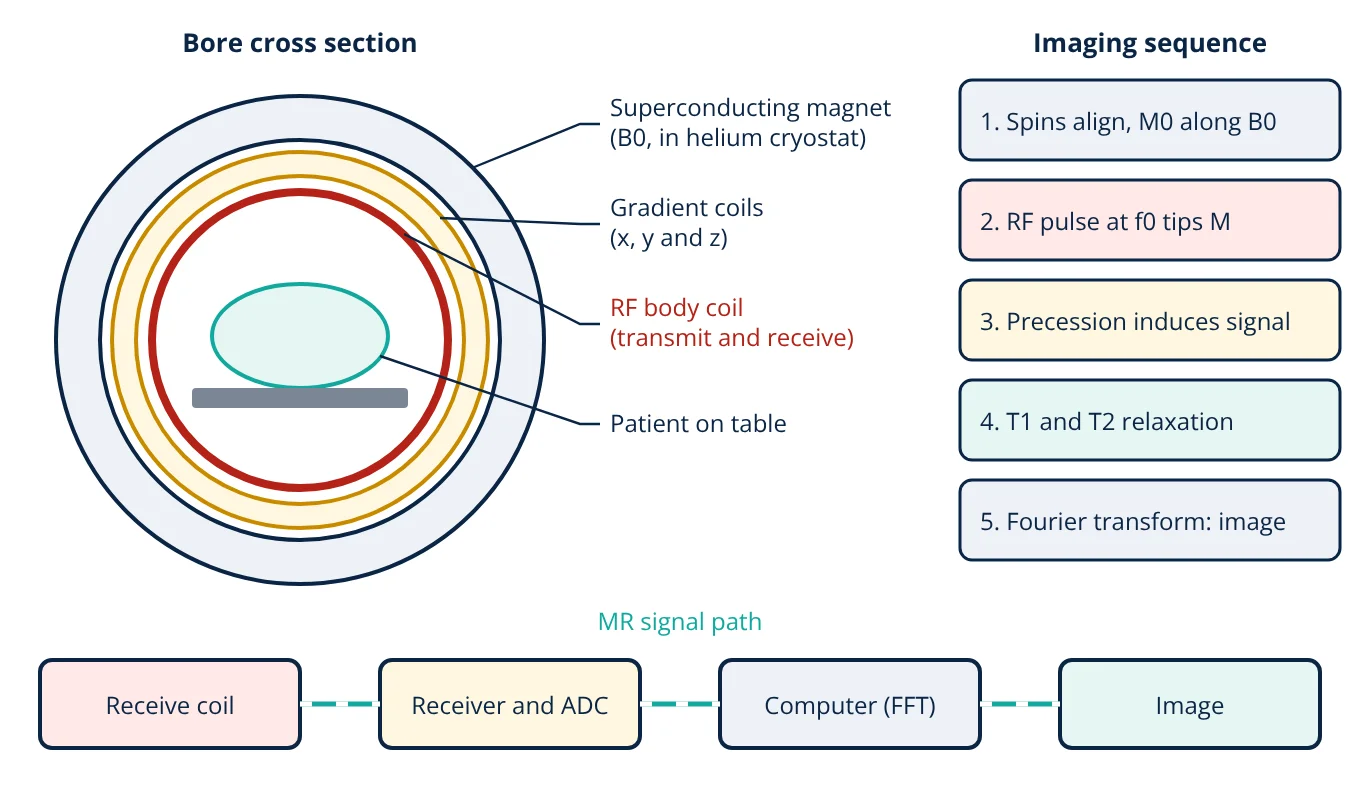
How MRI works: a strong magnetic field aligns hydrogen nuclei in the body, a radiofrequency pulse at their Larmor frequency tips them over, and as they precess and relax they induce a small signal in a receive coil. Gradient coils encode position into that signal, and a computer reconstructs the image by Fourier transform.
Magnetic resonance imaging (MRI) gives some of the best soft tissue contrast of any imaging method, without ionising radiation. Understanding how MRI works means following a chain of physics: nuclear magnetism, resonance, relaxation and Fourier encoding, all built on a large superconducting magnet. This article explains each step and the hardware behind it. For a comparison with X-ray, CT and ultrasound, see medical imaging modalities.
The physics behind MRI
The hydrogen nucleus is a single proton. It has a property called spin, which gives it a tiny magnetic moment, like a very small bar magnet. Hydrogen is ideal for imaging because the body contains a great deal of it in water and fat.
Outside a magnet, the moments point in random directions and cancel. Inside a strong static field B0, slightly more of them align with the field than against it. The small excess adds up to a net magnetisation M0 pointing along B0, conventionally called the z axis.
The moments do not simply line up; they precess around B0 like a spinning top in gravity. The precession frequency is the Larmor frequency:
For hydrogen, the gyromagnetic ratio divided by 2π is 42.58 MHz/T. At clinical field strengths of 1.5 T and 3 T, this puts the Larmor frequency in the radiofrequency (RF) band, which is why MRI uses RF coils and electronics similar to radio equipment.
Main components of an MRI scanner
- Superconducting magnet: produces the static field B0 along the bore. Its windings of niobium titanium wire are cooled by liquid helium to about 4 K, so they carry current with zero resistance and the field stays on permanently.
- Gradient coils: three sets of coils (x, y and z) that add a small, controllable field which varies linearly with position. Gradient strength is quoted in mT/m. Fast switching of these coils causes the loud knocking during a scan.
- RF coils: the body coil built into the bore transmits the RF pulse; dedicated local coils for the head, knee or spine sit close to the anatomy and receive the weak signal with better signal to noise ratio.
- RF system and receiver: a power amplifier drives the transmit coil, and a low noise receiver amplifies and digitises the returning signal. The digitiser must sample fast enough to satisfy the sampling theorem for the signal bandwidth.
- Shielding and computer: a Faraday cage (RF shield) around the scan room blocks external radio signals, and the computer controls the pulse sequence and reconstructs the images.
How MRI works step by step
- Alignment. The patient lies in B0 and a net magnetisation M0 builds up along z.
- Excitation. A short RF pulse at the Larmor frequency produces a weak rotating magnetic field B1. In resonance, it tips M away from z. A 90° pulse lays it fully into the transverse (xy) plane.
- Signal. The transverse magnetisation precesses at f0, and by Faraday’s law of induction it induces a voltage in the receive coil. This decaying signal is the free induction decay (FID), or an echo when refocusing pulses are used.
- Relaxation. The magnetisation returns to equilibrium through two processes, T1 and T2, which differ from tissue to tissue and give MRI its contrast.
- Encoding and reconstruction. Gradients make the frequency and phase of the signal depend on position. The digitised data fill a data matrix called k-space, and a 2D Fourier transform turns k-space into the image.
T1 and T2 relaxation and image contrast
T1 (spin lattice or longitudinal relaxation) describes how the z component of magnetisation recovers as the spins give energy back to their surroundings:
After one T1, Mz has recovered to about 63% of M0.
T2 (spin spin or transverse relaxation) describes how the transverse magnetisation decays as spins lose phase coherence through interactions with each other:
After one T2, the transverse magnetisation has fallen to about 37% of its starting value. T2 is always shorter than T1. Field inhomogeneity adds extra dephasing, so the observed FID decays with a shorter time constant called T2*; a spin echo uses a 180° refocusing pulse to reverse this extra dephasing.
The operator selects contrast with two timing parameters: the repetition time (TR) between excitations and the echo time (TE) from excitation to signal readout.
| Weighting | TR | TE | Appearance |
|---|---|---|---|
| T1-weighted | Short | Short | Fat bright, water (CSF) dark, good anatomy |
| T2-weighted | Long | Long | Water and fluid bright, good for oedema and lesions |
| Proton density | Long | Short | Contrast mainly from hydrogen concentration |
Spatial encoding with gradients
The Larmor equation shows that frequency follows the local field. When a gradient G is switched on, the field at position x becomes B0 + Gx, so each position precesses at its own frequency.
- Slice selection: a gradient during the RF pulse means only one slab of tissue is at resonance, so only that slice is excited.
- Frequency encoding: a readout gradient during signal acquisition maps one image direction to frequency.
- Phase encoding: a brief gradient before readout gives the other direction a position dependent phase. It is stepped through many values, one per line of k-space, which is the main factor setting scan time.
- Given
- Hydrogen, γ/2π = 42.58 MHz/T. Scanners at B0 = 1.5 T and 3 T. A frequency encoding gradient of 10 mT/m.
- Find
- The Larmor frequency at each field strength, and the frequency offset for tissue 0.10 m from the magnet centre along the gradient.
- Assumptions
- Perfectly uniform B0, linear gradient, chemical shift ignored.
- Solution
- f0 at 1.5 T = 42.58 × 1.5 = 63.87 MHz
f0 at 3 T = 42.58 × 3 = 127.74 MHz
Δf = (γ/2π) × G × x = 42.58 × 10⁶ Hz/T × 0.010 T/m × 0.10 m = 42 580 Hz - Answer
- About 63.9 MHz at 1.5 T and 127.7 MHz at 3 T; the gradient shifts tissue 0.10 m off centre by about 42.6 kHz
- Limitations
- Real magnets have small inhomogeneities and fat protons resonate at a slightly different frequency from water, which causes chemical shift artefacts.
The result shows why the RF system must be tuned to the field strength: a coil built for a 1.5 T scanner will not work on a 3 T scanner.
Key formulas for how MRI works
| Quantity | Formula | Symbols and units |
|---|---|---|
| Larmor frequency | f0 = (γ/2π) × B0 | f0 in MHz, γ/2π = 42.58 MHz/T for hydrogen, B0 in T |
| Frequency with gradient | f(x) = (γ/2π) × (B0 + G x) | G in T/m, x = position from isocentre in m |
| T1 recovery | Mz(t) = M0 (1 − e^(−t/T1)) | M0 = equilibrium magnetisation, t and T1 in ms |
| T2 decay | Mxy(t) = Mxy(0) e^(−t/T2) | T2 in ms, always shorter than T1 |
MRI safety
MRI does not use ionising radiation, but it has its own hazards, addressed by IEC 60601-2-33.
- Projectile effect: the static field strongly attracts ferromagnetic objects such as oxygen cylinders and tools, and it is always on. Access to the scan room is controlled and every patient is screened for implants and metal.
- RF heating: RF energy deposited in tissue is limited by the specific absorption rate (SAR). IEC 60601-2-33 sets whole body SAR limits of 2 W/kg in normal operating mode and 4 W/kg in first level controlled operating mode.
- Gradient switching: rapid changes of field (dB/dt) can stimulate peripheral nerves, so the standard limits gradient output.
- Acoustic noise: hearing protection is required.
- Quench: if the magnet loses superconductivity, the stored energy boils off the helium rapidly, which must be vented outside through a quench pipe.
MRI scanners are regulated medical devices; the regulatory side is covered in medical device classification. Like ECG and EEG systems in biopotential measurement, MRI depends on careful low noise signal acquisition.
Advantages and limitations
Advantages: excellent soft tissue contrast, no ionising radiation, images in any plane, and many contrast types (T1, T2, diffusion, flow) from the same scanner.
Limitations: long scan times compared with CT, high purchase and running cost, sensitivity to patient motion, loud noise, a confined bore, and contraindications for some implants.
How MRI works: interview and viva questions
- Why does MRI image hydrogen? Hydrogen is abundant in the water and fat of the body and its single proton gives a strong magnetic resonance signal.
- What is the Larmor frequency of hydrogen at 1.5 T? It is 42.58 MHz/T × 1.5 T, which is about 63.9 MHz.
- What is the difference between T1 and T2? T1 is the recovery time of longitudinal magnetisation as energy returns to the surroundings, while T2 is the decay time of transverse magnetisation through loss of phase coherence. T2 is always shorter than T1.
- What do the gradient coils do? They make the magnetic field, and therefore the precession frequency and phase, vary with position, which allows slice selection and spatial encoding of the signal.
- What is k-space? It is the matrix of digitised, spatially encoded signal data; a 2D Fourier transform of k-space gives the image.
Frequently asked questions
Does MRI use ionising radiation?
No. MRI uses a static magnetic field, switched magnetic field gradients and radiofrequency energy. None of these ionise tissue. The main safety concerns are attraction of ferromagnetic objects, RF heating of the body and implants, nerve stimulation from fast gradient switching and acoustic noise.
Why is an MRI scanner so loud?
The gradient coils carry large, rapidly switched currents inside the strong static field. The Lorentz forces on the coil conductors make them vibrate, which produces loud knocking and buzzing sounds. Patients are given ear plugs or headphones for hearing protection.
What is the difference between a 1.5 T and a 3 T MRI scanner?
The 3 T scanner has twice the static field, so the Larmor frequency doubles and the available signal is higher, which can be used for finer resolution or shorter scans. In exchange, RF heating, susceptibility artefacts and some implant restrictions are greater at 3 T.
References
- J. T. Bushberg, J. A. Seibert, E. M. Leidholdt and J. M. Boone, The Essential Physics of Medical Imaging, 4th ed., Wolters Kluwer, 2020
- D. W. McRobbie, E. A. Moore, M. J. Graves and M. R. Prince, MRI from Picture to Proton, 3rd ed., Cambridge University Press, 2017
- R. W. Brown, Y. C. N. Cheng, E. M. Haacke, M. R. Thompson and R. Venkatesan, Magnetic Resonance Imaging: Physical Principles and Sequence Design, 2nd ed., Wiley, 2014
- IEC 60601-2-33:2022 Medical electrical equipment, Part 2-33: Particular requirements for the basic safety and essential performance of magnetic resonance equipment for medical diagnosis
- A. Webb, Introduction to Biomedical Imaging, 2nd ed., Wiley-IEEE Press, 2022
Get one engineering email a week
New articles, worked examples and study notes every week. Free, no spam, unsubscribe any time.