Soil Moisture Sensors: Types and Working
Soil moisture sensors are instruments that measure how much water the soil holds, either as volumetric water content or as soil water tension. TDR and capacitance sensors infer water content from the soil dielectric permittivity, while tensiometers and resistance blocks measure how tightly water is held, which tells growers when to irrigate.
Soil moisture sensors are the eyes of a modern irrigation system. This article explains how each type of soil moisture sensor works, what it actually measures, how to calibrate and install it, and how to turn a reading into an irrigation decision.
What soil moisture sensors measure
Soil water can be described in two different ways, and every sensor measures one of them.
- Water content is the amount of water present. Gravimetric water content θg is the mass of water divided by the mass of oven dry soil. Volumetric water content θv is the volume of water per unit volume of soil (m³/m³), which is what irrigation calculations need.
- Soil water potential (also called tension or suction) is the energy with which the soil holds the water, in kPa. Plants feel tension, not content. Field capacity is commonly taken near 33 kPa of suction and the permanent wilting point near 1500 kPa.
The two are linked by the soil water retention curve, which differs for sand, loam and clay. The same 0.20 m³/m³ can be comfortably wet in a sand and severely dry in a clay, so content readings must always be interpreted against soil specific limits.
The reference method is gravimetric sampling: a sample is weighed, dried in an oven at 110 ± 5 °C to constant mass (ASTM D2216) and weighed again. It is used mainly to calibrate field sensors. Volumetric content follows from the dry bulk density:
How soil moisture sensors work: the main types
Dielectric sensors: why they work
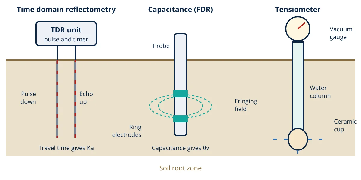
Most electronic soil moisture sensors exploit one physical fact: the relative permittivity (dielectric constant) of liquid water is about 80, while dry soil minerals are about 3 to 5 and air is 1. The bulk or apparent permittivity Ka of moist soil is therefore dominated by its water content. Measuring Ka gives θv with a calibration equation.
Time domain reflectometry (TDR)
A TDR probe has two or three parallel steel rods acting as a transmission line. The instrument sends a fast rising voltage pulse along the cable; the pulse travels down the rods, reflects at their open ends and returns. The propagation velocity is v = c ÷ √Ka, so the round trip time over rods of length L gives the permittivity:
Topp, Davis and Annan (1980) fitted a widely used empirical equation relating Ka to volumetric water content for many mineral soils:
TDR is accurate, needs little soil specific calibration in mineral soils and also measures bulk electrical conductivity from the signal attenuation. Its drawbacks are cost and signal loss in very saline or heavy clay soils. Organic and volcanic soils need their own calibration.
Capacitance and FDR sensors
Capacitance sensors place two electrodes (rings on an access tube, or flat plates or prongs) in the soil, which forms the dielectric of a capacitor. The capacitor is part of an oscillator circuit, so the oscillation frequency shifts as water content changes; such devices are often called frequency domain reflectometry (FDR) sensors. They are cheaper, use little power and suit data loggers and wireless nodes, which is why they dominate precision agriculture networks. Their sensing volume is small and concentrated near the electrodes, so air gaps cause large errors, and readings are more affected by salinity and temperature than TDR. A soil specific calibration against gravimetric samples is recommended.
Electrical resistance blocks
Gypsum blocks and granular matrix sensors contain two electrodes embedded in a porous material that comes into water equilibrium with the surrounding soil. As the soil dries, the block dries, and resistance between the electrodes rises. The reading is converted to soil water tension. They are cheap and suit the drier range but respond slowly. Bare metal prong sensors sold for hobby use measure soil resistance directly, which depends strongly on salt content, so they only give a rough wet or dry indication.
Tensiometers
A tensiometer is a sealed water filled tube with a porous ceramic cup at the bottom and a vacuum gauge or pressure transducer at the top. As the soil dries, water is drawn out through the cup into the soil, creating suction in the tube that equals the soil water tension. When the soil is wetted, water flows back in and the reading falls. Tensiometers measure what the plant feels and need no soil calibration, but they only work up to about 80 kPa of suction because the water column breaks (cavitates) beyond that.
Neutron probes
A neutron moisture meter lowers a radioactive source of fast neutrons into an access tube. Collisions with hydrogen nuclei, mostly in soil water, slow the neutrons, and a detector counts the slow (thermal) neutrons returning. The count rate rises with water content. It requires a radiation licence, so it is used mainly in research.
Comparison of soil moisture sensors
| Sensor | Measures | Strengths | Limitations |
|---|---|---|---|
| TDR | θv via Ka | Accurate, little calibration in mineral soils | Cost, signal loss in saline soils |
| Capacitance / FDR | θv via capacitance | Low cost, low power, easy logging | Small sensing volume, needs soil calibration |
| Resistance block | Tension via resistance | Cheap, durable, dry range | Slow response, gypsum dissolves |
| Tensiometer | Tension in kPa | Direct plant relevant reading, no calibration | Only to about 80 kPa, maintenance |
| Neutron probe | θv via hydrogen | Large sampling volume, accurate | Radiation licence, manual readings |
| Gravimetric | θg by mass | Reference method | Destructive, slow |
Worked example: TDR reading to irrigation depth
- Given
- A TDR probe with rods 0.20 m long measures a round trip travel time of 6.0 ns. The sensor represents a 300 mm root zone layer of a loam whose field capacity is θv = 0.40 m³/m³.
- Find
- The apparent permittivity, the volumetric water content using the Topp equation, the water stored in the layer and the depth needed to refill it to field capacity.
- Assumptions
- c = 3 × 10⁸ m/s; the Topp equation applies to this mineral soil; the reading is uniform over the layer.
- Solution
- Ka = (c t ÷ 2L)² = (3 × 10⁸ × 6.0 × 10⁻⁹ ÷ 0.40)² = 4.5² = 20.25
θv = −0.053 + 0.0292 × 20.25 − 0.00055 × 20.25² + 0.0000043 × 20.25³
θv = −0.053 + 0.5913 − 0.2255 + 0.0357 = 0.348 m³/m³
Stored water = 0.348 × 300 mm = 104.5 mm
Deficit = (0.40 − 0.348) × 300 mm = 15.5 mm - Answer
- Ka ≈ 20.3, θv ≈ 0.35 m³/m³, about 105 mm of water stored, and a net irrigation of about 15 mm refills the layer to field capacity
- Limitations
- The Topp equation can be off for clay, organic or saline soils; a single probe does not capture field variability, and gross irrigation must allow for application efficiency.
The deficit then feeds straight into an irrigation schedule, as shown in irrigation water requirement.
Key formulas for soil moisture sensors
| Quantity | Formula | Symbols and units |
|---|---|---|
| Gravimetric water content | θg = (m_wet − m_dry) ÷ m_dry | m in g, θg in g/g |
| Volumetric water content | θv = θg × ρb ÷ ρw | ρb = dry bulk density, ρw = water density, both in g/cm³ |
| TDR permittivity | Ka = (c t ÷ 2L)² | c = 3 × 10⁸ m/s, t = round trip time in s, L = rod length in m |
| Topp equation | θv = −0.053 + 0.0292 Ka − 0.00055 Ka² + 0.0000043 Ka³ | θv in m³/m³, Ka dimensionless |
| Stored water depth | D = θv × Z | Z = layer depth in mm, D in mm |
| Deficit to field capacity | d = (θ_FC − θv) × Z | θ_FC = field capacity in m³/m³, d in mm |
Installation and calibration
- Location: choose a spot representative of the irrigation zone, avoiding wheel tracks, low wet spots and field edges. Use at least two locations per zone.
- Depth: install in the active root zone, typically one sensor in the upper root zone and one near the bottom of the roots. For drip irrigation, place sensors in the wetted bulb near an emitter.
- Contact: sensors must touch undisturbed soil with no air gaps. Use the manufacturer’s installation tool or a slurry of native soil, and backfill carefully.
- Calibration: take gravimetric samples near the sensor at a wet and a dry state, convert to θv using bulk density, and fit a correction line to the sensor output.
- Signals: field sensors usually output an analogue voltage, 4 to 20 mA, SDI-12 or Modbus RS-485 for a logger or PLC, and many connect through LoRaWAN or cellular nodes.
- Checks: confirm readings rise after every irrigation or rain.
Using soil moisture sensors for irrigation
Readings are compared with soil limits. Irrigation starts when the root zone has used the management allowed depletion, a fraction of the available water between field capacity and wilting point, and stops before the soil passes field capacity, which would only cause drainage and nutrient leaching. With tensiometers, the trigger is a tension value suited to the crop and soil. This closed loop logic is described in automated irrigation control, and the trade-offs between delivery methods in drip vs sprinkler irrigation. FAO Paper 56 explains how the depletion fraction varies with crop and evaporative demand.
Soil moisture sensors interview and viva questions
- Why can permittivity be used to measure soil water content? Liquid water has a relative permittivity of about 80, far higher than dry soil minerals at about 3 to 5 and air at 1, so the bulk permittivity of soil depends mainly on its water content.
- What does a TDR instrument actually time? It times the round trip of a voltage pulse along the probe rods; the velocity equals c divided by the square root of Ka, so travel time gives the apparent permittivity.
- What is the difference between water content and water potential? Water content is how much water the soil holds, while water potential or tension is how strongly the soil holds it, which is what the plant roots must overcome.
- Why does a tensiometer stop working in dry soil? Beyond about 80 kPa of suction the water column in the tube cavitates and air enters through the ceramic cup, so the reading is lost until the instrument is refilled.
- Why must capacitance sensors be installed without air gaps? Their sensing volume is small and concentrated near the electrodes, and air has a permittivity of 1, so even a thin gap makes the soil appear much drier than it is.
Frequently asked questions
Which soil moisture sensor is most accurate?
Properly installed TDR probes and neutron probes calibrated for the site are generally regarded as the most accurate field methods for volumetric water content, with the gravimetric oven drying method used as the reference for calibrating all of them. Low cost capacitance sensors can also be accurate if they are calibrated for the specific soil.
Do cheap resistive soil moisture sensors work?
Bare two prong resistive sensors respond to moisture, but their reading also depends strongly on salt content and temperature, and the exposed metal corrodes when powered continuously. They suit hobby projects and simple wet or dry indication rather than quantitative irrigation scheduling.
How deep should soil moisture sensors be installed?
Sensors are placed in the active root zone of the crop, usually at two or more depths, for example one in the upper root zone to trigger irrigation and one near the bottom of the roots to detect deep drainage. Good contact with undisturbed soil and no air gaps around the sensor are essential.
References
- G. C. Topp, J. L. Davis and A. P. Annan, Electromagnetic determination of soil water content: Measurements in coaxial transmission lines, Water Resources Research, 16(3), 1980
- International Atomic Energy Agency, Field Estimation of Soil Water Content: A Practical Guide to Methods, Instrumentation and Sensor Technology, Training Course Series 30, IAEA, 2008
- USDA Natural Resources Conservation Service, National Engineering Handbook Part 652, Irrigation Guide, Chapter 9: Irrigation water management
- D. Hillel, Introduction to Environmental Soil Physics, Academic Press, 2004
- FAO Irrigation and Drainage Paper 56, Crop Evapotranspiration: Guidelines for Computing Crop Water Requirements, 1998
- ASTM D2216-19, Standard Test Methods for Laboratory Determination of Water (Moisture) Content of Soil and Rock by Mass
Get one engineering email a week
New articles, worked examples and study notes every week. Free, no spam, unsubscribe any time.