VLAN Explained: Types and Configuration Basics
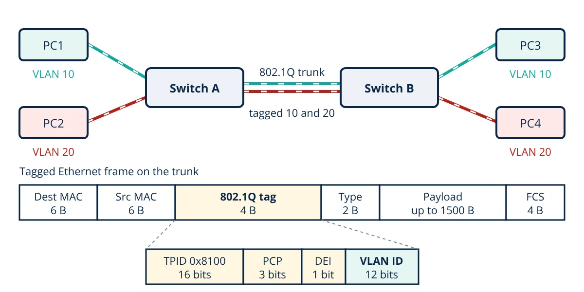
A VLAN (virtual local area network) splits one physical switched network into separate logical networks, each its own broadcast domain. Switches mark frames with an IEEE 802.1Q tag carrying a 12 bit VLAN ID. Access ports carry one untagged VLAN, trunk ports carry many tagged VLANs, and routers connect different VLANs.
Without a VLAN, every device connected to a group of switches is in one broadcast domain: a broadcast from any computer reaches all the others. As networks grow, this wastes bandwidth and mixes traffic that should be kept apart, such as office PCs, IP phones, cameras and building controllers. VLANs solve this in software, letting engineers group ports by function rather than by physical location.
What a VLAN does
A VLAN is a group of switch ports, and the devices on them, that behave as if they were on their own separate switch. A switch only forwards frames between ports in the same VLAN. Benefits include:
- Smaller broadcast domains: broadcasts such as ARP requests stay within one VLAN.
- Security and segmentation: sensitive systems are separated, and traffic between VLANs passes through a router or firewall where it can be filtered.
- Flexibility: a user can move desks and stay in the same VLAN by changing one port setting.
- Traffic separation and priority: voice, video and control traffic can be placed in their own VLANs and given quality of service treatment.
Switching and routing roles are compared in router vs switch. VLANs work at the data link layer (Layer 2) of the OSI model.
IEEE 802.1Q VLAN tagging
When frames for several VLANs share one link, the receiving switch must know which VLAN each frame belongs to. IEEE 802.1Q inserts a 4 byte tag after the source MAC address:
- TPID (16 bits): the value 0x8100, which identifies the frame as tagged.
- PCP (3 bits): priority code point, a class of service from 0 to 7 used for quality of service.
- DEI (1 bit): drop eligible indicator, marking frames that may be dropped first under congestion.
- VID (12 bits): the VLAN identifier. Values 0 and 4095 are reserved, so VLAN IDs 1 to 4094 are usable.
The tag raises the maximum Ethernet frame size from 1518 to 1522 bytes. The switch adds the tag when a frame enters a trunk and removes it before delivering the frame to an end device on an access port, so ordinary computers never see it.
Access, trunk and native VLAN ports
- Access port: belongs to one VLAN and carries untagged frames. Used for PCs, printers and most end devices.
- Trunk port: carries frames for many VLANs, each tagged with its VLAN ID. Used between switches, and between a switch and a router, firewall or server that supports tagging.
- Native VLAN: the one VLAN on a trunk whose frames are sent untagged. On Cisco switches it is VLAN 1 by default. Both ends of a trunk must agree on it.
Types of VLAN
- Default VLAN: VLAN 1 on most switches; all ports start in it and it cannot be deleted.
- Data (user) VLAN: carries normal user traffic, often one per department or function.
- Voice VLAN: carries IP phone traffic. A phone and a PC can share one port, with the phone tagging its own traffic in the voice VLAN and the PC using the untagged data VLAN.
- Management VLAN: used to reach switch management interfaces, kept separate from user traffic.
- Native VLAN: the untagged VLAN on a trunk, best set to an unused VLAN rather than VLAN 1.
VLAN membership is usually static, set per port. Dynamic assignment by MAC address or by IEEE 802.1X authentication places a device in a VLAN based on who it is.
Inter-VLAN routing
Because each VLAN is a separate broadcast domain, normally with its own IP subnet, traffic between VLANs must be routed:
- Router on a stick: one physical router interface connects to a switch trunk and is split into subinterfaces, one per VLAN, each with its own IP address as the default gateway.
- Layer 3 switch: a switched virtual interface (SVI) is created for each VLAN and the switch routes between them at hardware speed. This is the usual method in modern networks.
A firewall can also act as the gateway for sensitive VLANs so that traffic between them is inspected.
VLAN configuration basics
The example below uses Cisco IOS commands; other vendors use similar concepts with different syntax.
! Create VLANs
vlan 10
 name SALES
vlan 20
 name ENGINEERING
! Access port for a PC in VLAN 10
interface GigabitEthernet0/1
 switchport mode access
 switchport access vlan 10
! Trunk to the next switch
interface GigabitEthernet0/24
 switchport mode trunk
 switchport trunk allowed vlan 10,20
 switchport trunk native vlan 999
Check the result with show vlan brief and show interfaces trunk. Good practice is to allow only the VLANs that are needed on each trunk, disable automatic trunk negotiation on access ports, shut down unused ports and place them in an unused VLAN.
- Given
- An IEEE 802.1Q network carrying Ethernet frames with the maximum 1500 byte payload and the minimum 64 byte frame size.
- Find
- The number of usable VLAN IDs, the size of a maximum length frame without and with the tag, and the tag overhead for the maximum and minimum frames.
- Assumptions
- Standard Ethernet II framing: 14 byte header and 4 byte FCS; preamble and interframe gap not counted.
- Solution
- Usable VLAN IDs = 2¹² − 2 = 4096 − 2 = 4094
Untagged maximum frame = 14 + 1500 + 4 = 1518 bytes
Tagged maximum frame = 1518 + 4 = 1522 bytes
Overhead on maximum frame = 4 ÷ 1518 = 0.26%
Overhead on minimum frame = 4 ÷ 64 = 6.25% - Answer
- 4094 usable VLANs; frames grow from 1518 to 1522 bytes; the tag adds about 0.26% to large frames and 6.25% to minimum size frames
- Limitations
- Real link efficiency also depends on preamble, interframe gap and the mix of frame sizes.
Key formulas for VLAN
| Quantity | Formula | Symbols and units |
|---|---|---|
| Usable VLAN IDs | N = 2¹² − 2 = 4094 | 12 bit VID; 0 and 4095 reserved |
| Priority levels | 2³ = 8 | 3 bit PCP, values 0 to 7 |
| Maximum tagged frame | 14 + 4 + 1500 + 4 = 1522 | bytes: header, tag, payload, FCS |
| Tag overhead | 4 ÷ frame size | Fraction of frame length |
Beyond 4094 VLANs
Service providers and large data centres can run out of 4094 VLAN IDs. IEEE 802.1ad (Q-in-Q) adds an outer service tag, with TPID 0x88A8, around the customer tag. VXLAN, defined in RFC 7348, carries Layer 2 frames inside UDP packets with a 24 bit network identifier, giving about 16 million segments across routed data centre networks.
VLAN interview and viva questions
- What is a VLAN? It is a logical group of switch ports that forms its own broadcast domain, separate from other VLANs on the same physical switches.
- How many VLANs can 802.1Q support and why? 4094, because the VLAN ID field is 12 bits (4096 values) and the values 0 and 4095 are reserved.
- What is the difference between an access port and a trunk port? An access port carries untagged frames for one VLAN; a trunk port carries tagged frames for many VLANs.
- What is the native VLAN? It is the VLAN whose frames cross a trunk without a tag; both ends must use the same native VLAN.
- How do devices in different VLANs communicate? Through inter-VLAN routing, using a router on a stick with subinterfaces or a Layer 3 switch with one SVI per VLAN.
Frequently asked questions
Can two VLANs communicate with each other?
Not directly. Each VLAN is a separate broadcast domain and usually a separate IP subnet, so traffic between VLANs must be routed by a router or a Layer 3 switch. This is called inter-VLAN routing, and access lists or a firewall on that router can control which traffic is allowed.
What is the difference between a VLAN and a subnet?
A VLAN works at Layer 2 and groups switch ports into one broadcast domain. A subnet works at Layer 3 and groups IP addresses. In practice they are usually mapped one to one: each VLAN carries one IP subnet, and the router interface for that VLAN is the default gateway for the subnet.
What is VLAN hopping?
VLAN hopping is an attack in which a device sends traffic into a VLAN it should not reach. Common methods are switch spoofing, where an attacker negotiates a trunk, and double tagging, which abuses the native VLAN. Disabling trunk negotiation on access ports and using an unused VLAN as the native VLAN prevent both.
References
- IEEE Std 802.1Q-2022, IEEE Standard for Local and Metropolitan Area Networks: Bridges and Bridged Networks
- IEEE Std 802.3-2022, IEEE Standard for Ethernet
- W. Odom, CCNA 200-301 Official Cert Guide, Volume 1, Cisco Press
- Cisco Systems, Catalyst Switch Software Configuration Guide: Configuring VLANs
- J. F. Kurose and K. W. Ross, Computer Networking: A Top-Down Approach, 8th ed., Pearson, Section 6.4 Switched Local Area Networks
- IETF RFC 7348, Virtual eXtensible Local Area Network (VXLAN), 2014
Get one engineering email a week
New articles, worked examples and study notes every week. Free, no spam, unsubscribe any time.