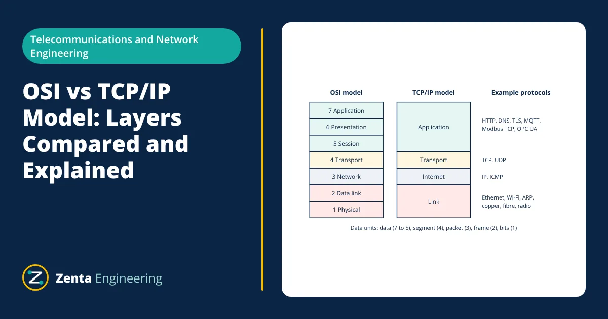
OSI vs TCP/IP Model: Layers Compared and Explained
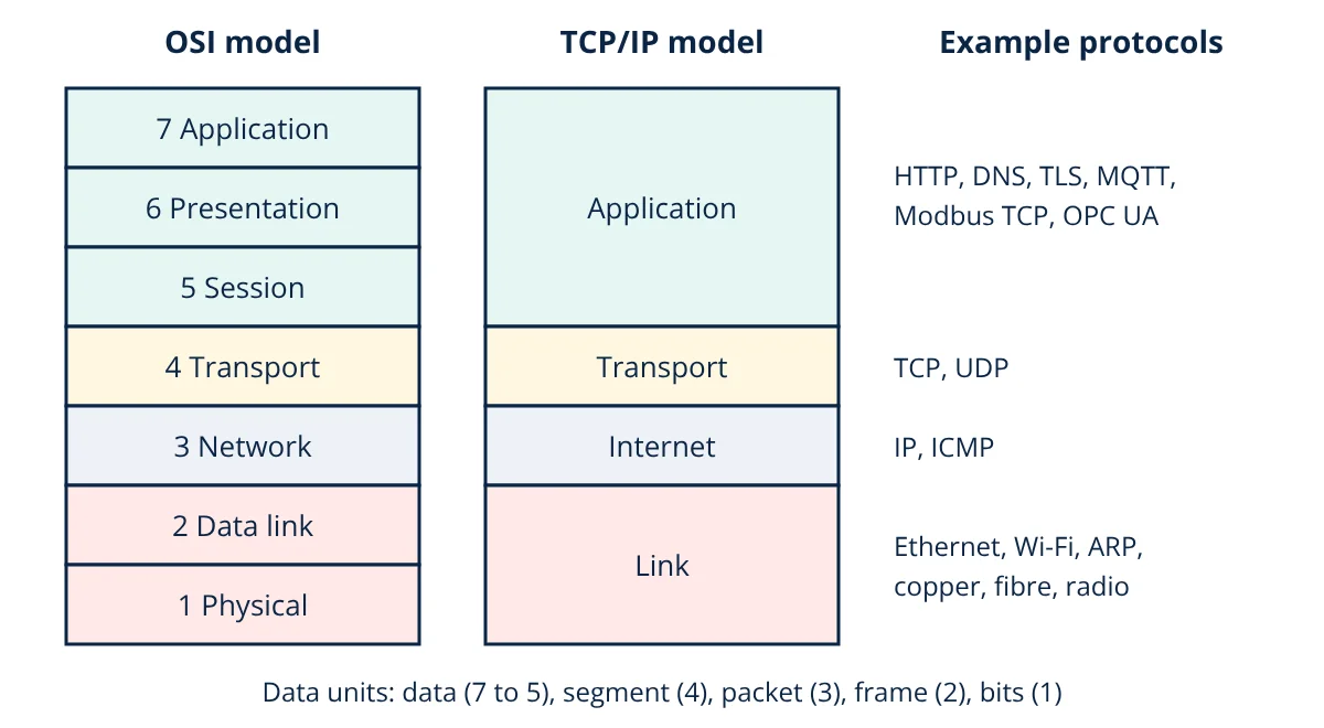
In OSI vs TCP/IP model comparisons, both describe how data moves through a network in layers. The OSI model has seven layers: physical, data link, network, transport, session, presentation and application. The TCP/IP model has four layers: link (network access), internet, transport and application. OSI is a reference model used for teaching and troubleshooting; TCP/IP is the protocol suite the internet and most industrial Ethernet networks actually run on.
Network communication is complex: electrical signals, addresses, error checks, retransmissions and application formats all have to work together. Layered models split this work so that each layer handles one job and relies on the layer below. That separation is why a web browser does not care whether the data travels over fibre, copper or Wi-Fi.
The OSI model: seven layers
The Open Systems Interconnection model was published by ISO in 1984 (ISO/IEC 7498). From bottom to top:
- Physical: transmits raw bits as electrical, optical or radio signals. Cables, connectors, voltage levels, fibre optics, hubs and repeaters.
- Data link: frames bits into frames, adds MAC addresses and an error check (CRC), and controls access to the medium. Ethernet, Wi-Fi MAC, PPP and switches.
- Network: logical addressing and routing between networks. IP, ICMP and routers.
- Transport: end to end delivery between applications, using port numbers. TCP gives reliable, ordered delivery; UDP gives fast, connectionless delivery.
- Session: opens, manages and closes sessions between applications.
- Presentation: data formats, encoding, compression and encryption, such as TLS and character encoding.
- Application: the protocols applications use directly: HTTP, DNS, SMTP, FTP, Modbus TCP and OPC UA.
A common memory aid from layer 1 upwards is “Please Do Not Throw Sausage Pizza Away”.
The TCP/IP model: four layers
The TCP/IP model grew out of ARPANET research in the 1970s and is defined in IETF documents such as RFC 1122. It is practical rather than theoretical, built around protocols that already worked:
- Link (network access): combines OSI physical and data link. Ethernet, Wi-Fi, ARP.
- Internet: IP addressing and routing, matching OSI layer 3.
- Transport: TCP and UDP, matching OSI layer 4.
- Application: combines OSI session, presentation and application. Applications handle their own formatting and sessions, for example HTTP over TLS.
Some textbooks show a five layer hybrid that keeps physical and data link separate, which is convenient for teaching.
Encapsulation: how data moves down and up the layers
When an application sends data, each layer adds its own header in front of the data it receives from above. This is encapsulation:
- The application produces a message, such as an HTTP request.
- The transport layer adds a TCP header with source and destination ports, forming a segment.
- The network layer adds an IP header with source and destination IP addresses, forming a packet.
- The data link layer adds an Ethernet header with MAC addresses and a trailer with a CRC, forming a frame.
- The physical layer sends the frame as bits.
The receiver reverses the process, each layer stripping its header and passing the payload up. Routers along the way only open the frame up to layer 3 to read the IP address; switches only look at layer 2. How these devices differ is covered in router vs switch.
OSI vs TCP/IP model: comparison
| Feature | OSI model | TCP/IP model |
|---|---|---|
| Number of layers | 7 | 4 (5 in some texts) |
| Developed by | ISO, published 1984 | US DoD research, IETF standards |
| Approach | Reference model first, protocols later | Protocols first, model describes them |
| Session and presentation | Separate layers | Part of the application layer |
| Physical and data link | Separate layers | Combined into link layer |
| Use today | Teaching, troubleshooting vocabulary | Internet and most real networks |
| Transport | Connection oriented and connectionless defined | TCP (reliable) and UDP (connectionless) |
- Given
- An HMI cannot read data from a PLC over Modbus TCP. The link light on the PLC port is on. A ping from the HMI to the PLC IP address succeeds, but the Modbus connection times out.
- Find
- Which layers are working and where to look next.
- Assumptions
- Both devices are on the same subnet.
- Solution
- Link light on: layer 1 is working
Ping succeeds: layers 2 and 3 work, because ARP resolved the MAC address and ICMP reached the PLC over IP
Modbus times out: the problem is at layer 4 or above. Check that TCP port 502 is open (not blocked by a firewall), that the PLC’s Modbus server is enabled, and that the unit ID and register addresses are correct - Answer
- Physical, data link and network layers are fine; troubleshoot transport (port 502) and the application settings
- Limitations
- Some devices block ping while still serving Modbus, so a failed ping does not always mean a layer 3 fault.
Why layered models matter
- Troubleshooting: working bottom up, layer by layer, quickly narrows down faults, as in the example above.
- Interoperability: vendors can build products for one layer that work with products from others at other layers.
- Independent change: Wi-Fi can replace Ethernet at the link layer without changing TCP or HTTP.
- Shared vocabulary: terms such as layer 2 switch, layer 3 routing and layer 7 firewall come from the OSI model.
Industrial networks and the layers
Industrial protocols fit the same structure. Modbus TCP, EtherNet/IP and OPC UA sit at the application layer on top of TCP or UDP and IP. PROFINET real time traffic skips IP and runs directly over Ethernet for speed. Serial fieldbuses such as Modbus RTU over RS-485 use only the physical, data link and application layers, as explained in Modbus RTU vs TCP. Layer 3 addresses, subnet masks and prefixes, which routers use to forward packets between networks, are covered in IP addressing and subnetting.
Understanding both models makes it easier to design, secure and troubleshoot any network, from an office LAN to a plant control system or a web service using HTTP.
Frequently asked questions
Which model is used in real networks, OSI or TCP/IP?
Real networks run the TCP/IP protocol suite. The OSI model is used as a teaching and troubleshooting reference because its seven layers separate functions more finely. Engineers often describe problems in OSI terms, such as a 'layer 2 issue', even on TCP/IP networks.
At which layer do switches and routers work?
A traditional switch works at layer 2, the data link layer, forwarding frames using MAC addresses. A router works at layer 3, the network layer, forwarding packets using IP addresses. Layer 3 switches combine both functions.
Is Modbus TCP an application layer protocol?
Yes. Modbus TCP carries Modbus messages as application data inside TCP segments on port 502. TCP, IP and Ethernet below it handle delivery, so in the OSI view Modbus TCP sits at layer 7.
References
- ISO/IEC 7498-1, Information technology: Open Systems Interconnection, Basic Reference Model
- IETF RFC 1122, Requirements for Internet Hosts: Communication Layers
- A. S. Tanenbaum and D. J. Wetherall, Computer Networks, 5th ed., Pearson
- J. F. Kurose and K. W. Ross, Computer Networking: A Top-Down Approach, 8th ed., Pearson
Get one engineering email a week
New articles, worked examples and study notes every week. Free, no spam, unsubscribe any time.