Optical Fiber Splicing: Fusion vs Mechanical
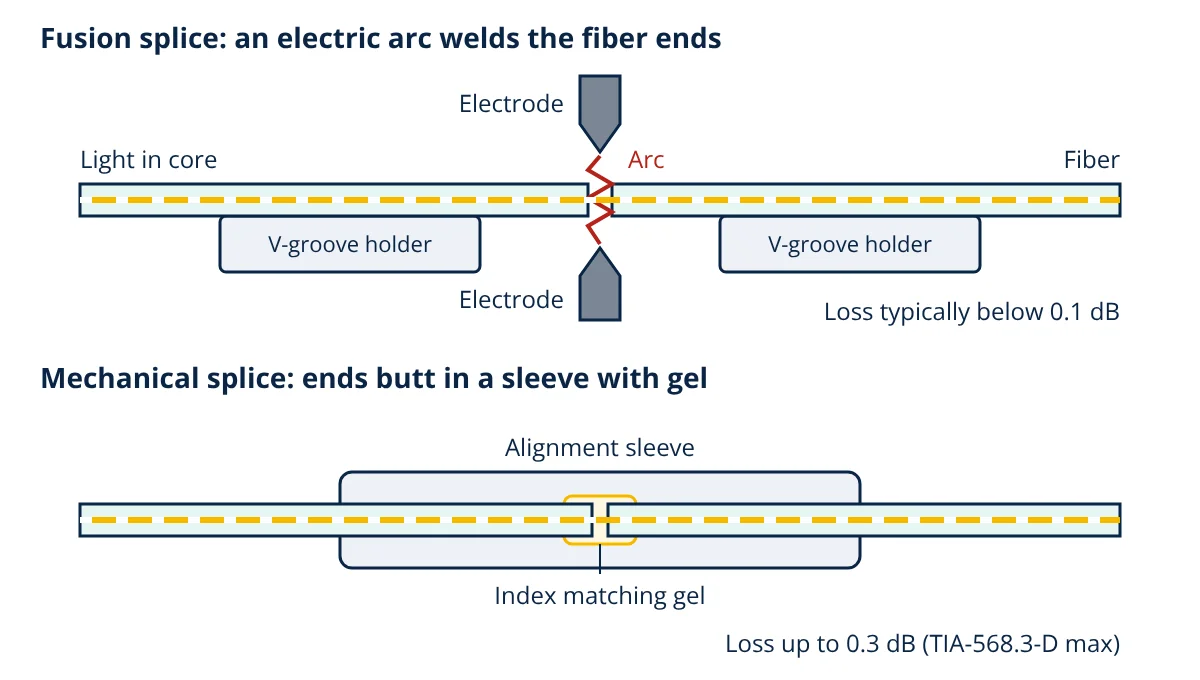
Fiber splicing is the permanent joining of two optical fibers so that light passes from one core into the next with minimal loss. Fusion splicing melts the aligned fiber ends together with an electric arc, giving very low loss and reflection. Mechanical splicing holds cleaved ends in an alignment sleeve with index matching gel, which is quicker but lossier.
Fiber splicing is needed whenever a link is longer than one cable reel, when a pigtail is joined to a trunk cable, or when a damaged cable must be repaired. The two methods, fusion and mechanical, both aim to line up two cores only a few micrometres across, but they do it in very different ways.
Why fiber splicing must be precise
A single-mode fiber to ITU-T G.652 has a mode field diameter of roughly 8.6 to 9.2 µm at 1310 nm inside a 125 µm cladding (see single-mode vs multimode fiber). Light only crosses a joint efficiently if the two light carrying regions overlap almost perfectly. Keiser and Hecht list the main causes of splice loss:
- Lateral offset: the core axes are displaced sideways.
- Angular misalignment: the fiber axes meet at an angle, often from a poor cleave.
- End gap: an air gap between the end faces causes Fresnel reflection at each glass and air surface.
- Intrinsic mismatch: the two fibers have different mode field diameters, core sizes or numerical apertures. No amount of alignment removes this part.
For a single-mode fiber with an approximately Gaussian mode of radius w, the loss from a lateral offset d is approximately:
With w about 4.6 µm, an offset of only 1 µm already costs about 0.2 dB. This is why splicing tools must align fibers to a fraction of a micrometre.
How fusion splicing works
A fusion splicer is a precision machine that aligns two fibers and welds them with an electric arc.
- Strip and clean: the coating is removed and the bare glass is cleaned with alcohol.
- Cleave: a precision cleaver scores and breaks the fiber to give a flat end face almost perpendicular to the axis.
- Load and align: each fiber is clamped in a V-groove holder. Cladding alignment machines rely on the precise V-grooves; core alignment machines use cameras and motors to image the cores and move them into line.
- Fuse: two electrodes strike an arc that heats the ends to their softening point while the fibers are pushed together, forming one continuous piece of glass.
- Estimate and protect: the splicer images the joint and estimates its loss, then the bare splice is covered with a heat shrink splice protector containing a strength member, the type of protector covered by IEC 61073-1.
Because the joint is solid glass with no gap, a fusion splice has essentially no Fresnel reflection, and its loss is typically below 0.1 dB.
How mechanical splicing works
A mechanical splice is a small housing that aligns two fibers without melting them. The fiber is stripped, cleaned and cleaved exactly as for fusion splicing. Each end is then pushed into the splice until the two faces meet in the middle of an alignment element, usually a precision V-groove or a fine capillary sleeve. A clamp or cam then grips the fibers.
The small gap left between the faces is filled with index matching gel, whose refractive index is close to that of glass. Without it, each glass and air surface would reflect light. Using the Fresnel formula with a glass index of 1.47:
That is about 3.6% reflected, or about 0.16 dB lost at each surface. The gel removes most of this, but a mechanical splice still reflects more than a fusion splice, and its loss is typically a few tenths of a dB. TIA-568.3-D allows up to 0.3 dB per splice of either type.
Fiber splicing comparison table
| Feature | Fusion splice | Mechanical splice |
|---|---|---|
| Joining method | Ends melted together by an electric arc | Ends butted in an alignment sleeve, held by a clamp |
| Typical loss | Below 0.1 dB | A few tenths of a dB |
| Reflectance | Essentially none | Higher, limited by the index matching gel |
| Strength and stability | Continuous glass, very stable once protected | Depends on the clamp and gel over time and temperature |
| Equipment | Cleaver and fusion splicer (high cost) | Cleaver and simple assembly tool (low cost) |
| Cost per splice | Low consumables, sleeve only | Each splice is a purchased part |
| Skill and power | Training and a powered machine | Little training, no power needed |
| Typical use | Backbone, outside plant, FTTH, high speed links | Restoration, small jobs, temporary links |
Differences explained
Loss and reflectance. Fusion splices have lower loss because the glass becomes one piece and the arc surface tension even helps pull small offsets into line. With no gap there is no reflection. Mechanical splices depend on the cleave and alignment quality, and the gel only partly hides the end faces. Low reflectance matters for high speed laser systems and analogue video, where reflected light disturbs the source.
Long term reliability. A protected fusion splice behaves like the fiber itself. A mechanical splice relies on the clamp and on gel that can change with temperature and age, so IEC 61073-1 defines environmental and mechanical test requirements for both mechanical splices and fusion splice protectors.
Cost. A fusion splicer is a large investment, but each splice then costs little more than a protection sleeve. Mechanical splices need only a cleaver and cheap tools, but each splice is a separate component. For crews doing many splices, fusion is cheaper overall; for a technician making occasional repairs, mechanical is often cheaper.
Measurement. Splice loss is usually verified with an OTDR. Because fibers with different mode field diameters backscatter differently, ITU-T G.652 tolerances alone can make a splice look slightly better from one end than the other. Using the formula below for mode field radii of 4.6 and 4.3 µm gives an intrinsic loss of only about 0.02 dB, yet OTDR readings can differ much more than that between directions, so best practice is to measure from both ends and average.
When to use which fiber splicing method
Use fusion splicing for:
- Outside plant and backbone cables, where ANSI/TIA-758-B and network operators expect permanent low loss joints in closures.
- Long haul, metro and FTTH networks with many splices per link.
- Splice-on pigtails and connectors in patch panels.
- High speed or reflection sensitive systems, such as the links behind 5G network architecture fronthaul.
Use mechanical splicing for:
- Emergency restoration until a permanent fusion splice can be made.
- A few splices in a building where buying a fusion splicer is not justified.
- Places where an arc is not acceptable or power is unavailable.
- Temporary or test connections.
Whichever method is used, the cabling sits at the physical layer of the OSI model and feeds switches and routers explained in router vs switch.
- Given
- A 10 km outside plant single-mode link at 1310 nm. Cable attenuation 0.5 dB/km (TIA-568.3-D maximum for outside plant single-mode cable). Two mated connector pairs at 0.75 dB each (TIA-568.3-D maximum). Six splices: four between 2 km cable reels and one pigtail splice at each end. Available transceiver power budget 11 dB, with a required safety margin of 3 dB.
- Find
- The total link loss with all fusion splices and with all mechanical splices, and whether each design fits the power budget.
- Assumptions
- Fusion splices taken at a conservative design value of 0.1 dB each; mechanical splices taken at the TIA-568.3-D maximum of 0.3 dB each; dispersion is not limiting at this distance.
- Solution
- Cable: 10 × 0.5 = 5.0 dB
Connectors: 2 × 0.75 = 1.5 dB
Fusion splices: 6 × 0.1 = 0.6 dB
Mechanical splices: 6 × 0.3 = 1.8 dB
Fusion design with margin: 5.0 + 1.5 + 0.6 + 3.0 = 10.1 dB
Mechanical design with margin: 5.0 + 1.5 + 1.8 + 3.0 = 11.3 dB - Answer
- The fusion spliced link needs 10.1 dB and fits the 11 dB budget with 0.9 dB spare; the mechanical spliced link needs 11.3 dB and exceeds the budget by 0.3 dB
- Limitations
- Maximum values from the standard are used for cable, connectors and mechanical splices, so real installed loss is usually lower; the link must still be verified with a loss test set and OTDR after installation.
Key formulas for fiber splicing
| Quantity | Formula | Symbols and units |
|---|---|---|
| Lateral offset loss | L ≈ 4.34 (d / w)² | L in dB, d = core offset in µm, w = mode field radius in µm |
| Fresnel reflection | R = ((n₁ − n) / (n₁ + n))² | n₁ = glass index, n = index of the gap medium (1.0 for air) |
| Mode field mismatch loss | L = −20 log₁₀ (2 w₁ w₂ / (w₁² + w₂²)) | w₁, w₂ = mode field radii of the two fibers |
| Total splice loss | L_splices = N × L_s | N = number of splices, L_s = loss per splice in dB |
| Link loss | L = α ℓ + N_c L_c + N_s L_s | α in dB/km, ℓ in km, L_c = connector pair loss, L_s = splice loss |
Fiber splicing interview and viva questions
- What is the main difference between fusion and mechanical splicing? Fusion splicing melts the two fiber ends into one piece with an electric arc, while mechanical splicing holds them end to end in an alignment sleeve with index matching gel.
- Why is index matching gel used in a mechanical splice? It fills the gap between the end faces with a material close to the glass index, which greatly reduces Fresnel reflection and loss at the joint.
- What is the maximum splice loss allowed by TIA-568.3-D? 0.3 dB per splice, for both fusion and mechanical splices.
- Why are single-mode splices so sensitive to lateral offset? The mode field is only about 9 µm across, and offset loss grows with the square of the offset divided by the mode field radius, so 1 µm of offset costs about 0.2 dB.
- Why is OTDR splice loss measured from both ends? Differences in mode field diameter change the backscatter level, making a splice appear as a gain or excess loss from one end; averaging both directions gives the true loss.
Frequently asked questions
Is fusion splicing always better than mechanical splicing?
For loss and reflectance, yes: a good fusion splice is lower loss, has almost no back reflection and is as strong and stable as the fiber itself once protected. Mechanical splices still make sense for emergency restoration, small jobs and places where an arc splicer cannot be used, because the tools are simple and cheap.
Why does an OTDR sometimes show a splice with a gain?
An OTDR reads splice loss from the change in backscattered light. If the fiber after the splice has a larger mode field diameter, it backscatters more strongly, so the splice can look like a gain from one direction and a larger loss from the other. Averaging the readings from both directions gives the true splice loss.
What is the maximum allowed splice loss in structured cabling?
TIA-568.3-D sets a maximum of 0.3 dB per splice, for both fusion and mechanical splices, and this is the value normally used in loss budgets for premises cabling. Well made fusion splices are usually far below this limit.
References
- TIA-568.3-D (2016), Optical Fiber Cabling and Components Standard, Telecommunications Industry Association
- ANSI/TIA-758-B (2012), Customer-Owned Outside Plant Telecommunications Infrastructure Standard
- IEC 61073-1:2009, Fibre optic interconnecting devices and passive components, Mechanical splices and fusion splice protectors for optical fibres and cables, Part 1: Generic specification
- ITU-T G.652 (11/2016), Characteristics of a single-mode optical fibre and cable
- G. Keiser, Optical Fiber Communications, 5th ed., McGraw-Hill, 2015
- J. Hecht, Understanding Fiber Optics, 5th ed., Pearson Prentice Hall, 2006
Get one engineering email a week
New articles, worked examples and study notes every week. Free, no spam, unsubscribe any time.