Oil and Gas Separators: Types and Working
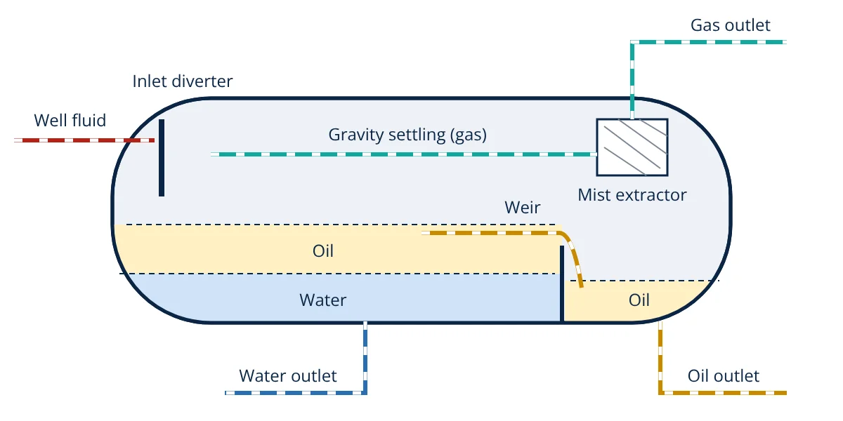
Oil and gas separators are pressure vessels that split a well stream into gas, oil and often water. An inlet diverter removes bulk liquid, gravity settles droplets and bubbles, and a mist extractor cleans the outlet gas. They are built as vertical, horizontal or spherical vessels, in two phase or three phase designs.
Oil and gas separators are the first major equipment a well stream meets at the surface. Fluid arrives from the wellhead as a mixture of gas, oil, water and sometimes sand, and nothing downstream (compressors, pipelines, storage tanks or the LNG process) works well until the phases are split. A separator does this mostly with gravity, time and a few well chosen internals, inside a vessel designed to the same principles as other pressure vessels.
What oil and gas separators do
API Specification 12J describes the separator as a vessel that removes liquid from gas and gas from liquid. In practice it must:
- Remove nearly all liquid droplets from the gas, so compressors and gas lines stay dry.
- Release gas bubbles trapped in the oil, so the oil is stable when it reaches tanks.
- In three phase service, split free water from oil.
- Hold a steady pressure and liquid levels, and absorb slugs of liquid arriving from the flowline.
Separation relies on density difference. Gas is much lighter than oil, and oil is lighter than water, so with enough time and calm flow each phase rises or falls into its own zone.
Parts of a separator
Stewart and Arnold divide a separator into four functional sections:
- Inlet diverter: a baffle plate, half pipe or cyclone at the inlet. The sudden change of momentum knocks out most of the liquid and starts the gas and liquid split.
- Gravity settling section: the gas space where the gas velocity is kept low enough for liquid droplets to fall out.
- Liquid collecting section: the lower part of the vessel, which gives retention time for gas to leave the liquid and, in three phase vessels, for oil and water to separate.
- Mist extractor: a wire mesh pad, vane pack or cyclone bank before the gas outlet that coalesces the small droplets that gravity alone would not catch.
Other internals include vortex breakers on liquid outlets, wave breakers and baffles in long horizontal vessels, sand jets for solids removal and, in three phase designs, a weir or oil bucket that sets the oil and water levels.
How oil and gas separators work
- Primary separation: the well stream strikes the inlet diverter. Liquid falls to the bottom and gas turns into the upper space.
- Gas settling: gas flows slowly along the vessel. Droplets settle when their terminal velocity exceeds the vertical velocity component of the gas (vertical vessel) or when they fall below the liquid surface before reaching the outlet (horizontal vessel).
- Mist removal: the mist extractor catches remaining fine droplets, which drain back to the liquid.
- Liquid retention: gas bubbles rise out of the liquid. In three phase service, water droplets fall through the oil layer and oil droplets rise through the water.
- Discharge: a pressure control valve on the gas line holds vessel pressure, a level controller and dump valve remove oil, and an interface level controller removes water. Interface and level measurement is often done with differential pressure, as explained in this guide to DP transmitter level measurement.
Safety devices follow API RP 14C practice: a pressure safety valve, high and low pressure shutdowns, and high and low level shutdowns that close the inlet or outlet valves.
Types of oil and gas separators
By shape
| Type | Strengths | Limitations | Typical use |
|---|---|---|---|
| Vertical | Small footprint, handles sand, level control less sensitive | Less gas liquid interface area, taller | High gas to liquid ratio, scrubbers, compressor suction |
| Horizontal | Large interface area, good for foaming crude and oil and water separation | Larger plot area, harder to remove sand | High liquid loads, three phase service |
| Spherical | Compact, cheap for small duty | Very limited liquid surge capacity | Small high pressure gas wells |
By function
- Two phase separators: gas and total liquid.
- Three phase separators: gas, oil and water.
- Test separators: measure the production of individual wells, with meters on each outlet.
- Production separators: handle the combined flow of several wells, often in high, intermediate and low pressure stages to stabilise the oil.
- Free water knockouts: remove large volumes of free water ahead of the main separation train.
- Scrubbers and knockout drums: vertical vessels for gas with small amounts of liquid, for example upstream of compressors.
- Slug catchers: vessels or pipe fingers at the end of long multiphase pipelines that absorb liquid slugs, often after pipeline pigging.
Equations used in separator sizing
Gas capacity is set by the Souders-Brown equation, which gives the maximum allowable gas velocity for droplets to separate:
The GPSA Engineering Data Book gives K values of about 0.055 to 0.107 m/s (0.18 to 0.35 ft/s) for vertical separators with a wire mesh mist extractor, and 0.12 to 0.15 m/s (0.40 to 0.50 ft/s) for horizontal ones, with derating for high pressure or difficult service. Liquid capacity is set by retention time: liquid volume equals liquid flow rate multiplied by the required time. API 12J suggests two phase retention times of about 1 minute for oil above 35 °API, 1 to 2 minutes for 20 to 30 °API and 2 to 4 minutes for 10 to 20 °API. Three phase vessels need longer, ideally based on laboratory or field data.
- Given
- A vertical two phase separator with a wire mesh pad. Actual gas flow at operating conditions 0.50 m³/s, gas density 50 kg/m³, oil density 800 kg/m³, K = 0.107 m/s. Liquid flow 0.020 m³/s with 1 minute retention time.
- Find
- Maximum gas velocity, minimum vessel diameter for gas capacity, and the liquid retention volume.
- Assumptions
- Clean service, no derating of K; gas flows upward through the full vessel cross section.
- Solution
- V_max = 0.107 × √((800 − 50) ÷ 50) = 0.107 × √15 = 0.107 × 3.873 = 0.414 m/s
A = 0.50 ÷ 0.414 = 1.207 m²
D = √(4 × 1.207 ÷ π) = 1.24 m
Liquid volume = 0.020 × 60 = 1.2 m³ - Answer
- Gas velocity at most 0.414 m/s, a minimum internal diameter of about 1.24 m, and 1.2 m³ of liquid retention volume below the normal liquid level
- Limitations
- A full design also adds surge volume, height for the inlet, disengagement space and mist pad, checks slenderness ratio, and derates K for high pressure, foaming or fouling service.
Key formulas for oil and gas separators
| Quantity | Formula | Symbols and units |
|---|---|---|
| Maximum gas velocity (Souders-Brown) | V_max = K √((ρ_L − ρ_G) ÷ ρ_G) | V_max and K in m/s, densities in kg/m³ |
| Required gas flow area | A = Q_G ÷ V_max | Q_G = actual gas flow, m³/s; A in m² |
| Vertical vessel diameter | D = √(4A ÷ π) | D in m |
| Liquid retention volume | V_L = Q_L × t | Q_L in m³/s, t = retention time in s |
| Droplet settling velocity (Stokes law) | V_t = g Δρ d² ÷ (18 μ) | d = droplet diameter, m; μ = continuous phase viscosity, Pa·s |
Selection points and maintenance
When selecting a separator, engineers look at the gas to liquid ratio, expected slugging, foaming tendency, emulsions, sand production, operating pressure, available plot space and whether water must be removed. Downstream, the lift method matters too: gas lift wells, covered in artificial lift methods, send large volumes of gas to the separator.
Maintenance focuses on keeping the internals and controls healthy: inspect and clean mist pads that plug with wax or scale, flush sand from the bottom, test pressure safety valves and shutdown functions, calibrate level and interface instruments, and inspect the vessel for corrosion and erosion near the inlet.
Oil and gas separators interview and viva questions
- What are the four sections of a separator? The inlet diverter, gravity settling section, liquid collecting section and mist extractor, each handling a different stage of separation.
- What does the Souders-Brown equation determine? It gives the maximum gas velocity at which liquid droplets can still settle, which sets the minimum vessel cross section for gas capacity.
- When is a vertical separator preferred? When the gas to liquid ratio is high, plot space is limited or sand is present, as in scrubbers and compressor suction drums.
- How is water removed in a three phase separator? Water settles below the oil, and an interface level controller opens the water dump valve to hold the oil and water interface at its set point.
- Why are mist extractor pads inspected regularly? Wax, scale or solids can plug the mesh, raising pressure drop and causing liquid carryover into the gas outlet.
Frequently asked questions
What is the difference between a two phase and a three phase separator?
A two phase separator splits the well stream into gas and total liquid. A three phase separator also separates the liquid into oil and free water, using extra retention time, an interface level control and usually a weir or bucket so each liquid leaves through its own outlet.
Why are horizontal separators used for three phase service?
A horizontal vessel gives a large liquid surface area and a long path for droplets to settle, which helps oil and water separate and gas bubbles escape from foamy crude. Vertical vessels suit high gas to liquid ratios and small footprints, but offer less interface area for oil and water separation.
What does the mist extractor do?
The mist extractor, often a wire mesh pad or vane pack near the gas outlet, catches small liquid droplets that the gravity section cannot settle. Droplets collide with the wires or vanes, coalesce into larger drops and drain back to the liquid section, so the outlet gas carries very little liquid.
References
- API Specification 12J, Specification for Oil and Gas Separators, American Petroleum Institute
- M. Stewart and K. Arnold, Surface Production Operations, Vol. 1: Design of Oil Handling Systems and Facilities, 3rd ed., Gulf Professional Publishing
- GPSA Engineering Data Book, Section 7: Separation Equipment, Gas Processors Suppliers Association
- API RP 14C, Analysis, Design, Installation and Testing of Safety Systems for Offshore Production Facilities
- J. D. Clegg (ed.), Petroleum Engineering Handbook, Vol. III: Facilities and Construction Engineering, SPE
Get one engineering email a week
New articles, worked examples and study notes every week. Free, no spam, unsubscribe any time.