Pressure Vessels: Types, Parts and Design Basics
Pressure vessels are closed containers designed to hold gases or liquids at a pressure substantially different from the surroundings. They are usually cylinders closed by curved heads, fitted with nozzles, manways and supports. Wall thickness is set by the hoop stress σ = PD / 2t, using code formulas such as those in ASME Section VIII, plus a corrosion allowance. Every vessel is pressure tested and protected by a relief device.
Reactors, distillation columns, separators, receivers, storage bullets and heat exchanger shells are all pressure vessels. Because a failure can release large amounts of energy and hazardous material, their design, fabrication, inspection and testing are governed by codes and, in most countries, by law. This article explains the basic types, parts and design ideas that every process engineer should know.
Types of pressure vessels
- By shape: cylindrical vessels are the most common because they are easy to fabricate and fit plant layouts; spherical vessels need the least wall thickness for a given volume and pressure and are used for large gas storage, but cost more to build.
- By orientation: vertical vessels save plot space and suit columns and reactors; horizontal vessels suit separators, storage bullets and drums where liquid surface area matters.
- By pressure: internal pressure vessels are the usual case; vacuum and external pressure vessels must be checked against buckling, often needing stiffening rings.
- By wall construction: thin wall (thickness small compared with diameter) for most process work; thick wall and multilayer vessels for very high pressures.
- By function: storage vessels, process vessels (reactors, columns, separators), heat exchanger shells and boilers (fired vessels, under separate rules).
Main parts of a pressure vessel
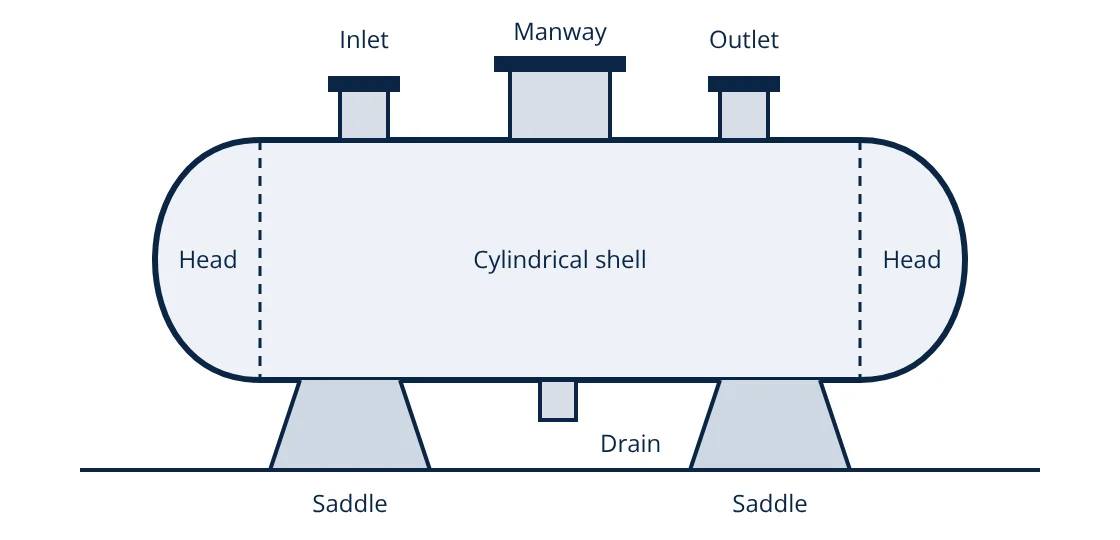
- Shell: the main cylindrical body, made of rolled and welded plate or seamless pipe for small diameters.
- Heads (end closures): hemispherical (strongest, thinnest, most expensive to form), 2:1 semi-ellipsoidal (the most common compromise), torispherical (cheaper, for lower pressures), conical (for drainage or transitions) and flat (only for small diameters or low pressures, because they need very thick plate).
- Nozzles: connect piping and instruments. Openings weaken the shell, so the code requires area replacement by thicker nozzle necks or reinforcing pads.
- Manways and handholes: allow entry for inspection and maintenance.
- Supports: saddles for horizontal vessels; skirts, legs or lugs for vertical vessels. Supports must carry weight, contents, wind and earthquake loads.
- Internals: trays, baffles, demisters, coils and distributors depending on the duty.
Stresses in a thin cylindrical shell
Internal pressure P in a cylinder of diameter D and wall thickness t produces two principal membrane stresses:
The hoop (circumferential) stress is twice the longitudinal stress, so longitudinal weld seams are the more critical. In a sphere, the stress is PD / 4t in every direction, which is why spheres and hemispherical heads need about half the thickness of a cylinder. These are direct applications of stress and strain to a pressurised shell.
Thickness by the ASME code formula
ASME Section VIII Division 1 gives the minimum required thickness of a cylindrical shell under internal pressure (circumferential stress, thin wall range) as:
R is the inside radius, S the maximum allowable stress of the material at design temperature (from the code tables), and E the joint efficiency, which depends on the type of weld and the extent of radiography. A corrosion allowance is added, and the result is rounded up to an available plate thickness, also allowing for mill under-tolerance and forming thinning.
- Given
- A cylindrical vessel with inside diameter 1000 mm, design pressure 1.5 MPa (gauge). Allowable stress from the code tables for the chosen material at design temperature S = 138 MPa. Joint efficiency E = 0.85 (spot radiography). Corrosion allowance 3 mm.
- Find
- The required shell thickness.
- Assumptions
- Internal pressure only; thin wall formula valid; no external loads.
- Solution
- R = 500 mm
t = 1.5 × 500 / (138 × 0.85 − 0.6 × 1.5) = 750 / (117.3 − 0.9) = 750 / 116.4 = 6.44 mm
With corrosion allowance: 6.44 + 3 = 9.44 mm - Answer
- Minimum 9.44 mm, so a 10 mm plate would normally be selected, subject to tolerance and code minimum thickness checks
- Limitations
- Heads, nozzle reinforcement, wind, seismic, nozzle loads and external pressure must be checked separately. Only a qualified designer working to the full code can certify a vessel.
The code approach builds in a margin through the allowable stress, which is a fraction of the material’s tensile and yield strength. This is the same idea as the factor of safety in machine design.
Vacuum and external pressure
Vessels under vacuum or external pressure fail by buckling, not by yielding. Their wall thickness depends on the diameter, the length between stiffeners and the material’s elastic modulus, and the code provides charts for the allowable external pressure. Stiffening rings are a cheaper way to resist buckling than a much thicker shell. Many vessels see vacuum during steam out or draining, so this case should always be checked.
Fabrication, testing and inspection
- Materials: carbon steel for most duties; stainless steels, alloy steels and clad plate for corrosion, low temperature or high temperature service. Material certificates must trace each plate.
- Welding: qualified procedures and welders; joints examined by radiography or ultrasonic testing to the extent the design assumes.
- Post weld heat treatment: relieves residual stresses where thickness or service requires it.
- Pressure test: ASME Section VIII Division 1 requires a hydrostatic test, generally at 1.3 times the MAWP adjusted for the stress ratio between test and design temperature. Pneumatic testing at a lower factor is allowed only where hydrotesting is impractical.
- Nameplate and documentation: design data, code stamp and test records.
Safety in operation
- Pressure relief: every vessel needs a relief valve or rupture disc sized for the worst credible overpressure case, set no higher than the MAWP.
- Instrumentation: pressure measurement, level and temperature indication with alarms and trips.
- Periodic inspection: wall thickness surveys, internal inspection and statutory examinations in line with local regulations.
- Changes: never weld, modify or re-rate a vessel without engineering approval.
Pressure vessels appear throughout the plant: reactors such as CSTRs and PFRs, distillation columns and heat exchanger shells are all designed this way.
Frequently asked questions
What is the difference between design pressure and operating pressure?
Operating pressure is the pressure the vessel normally sees in service. Design pressure is set higher, to cover upsets and the set pressure of the relief device, and is the value used to calculate thickness. The maximum allowable working pressure (MAWP) is the highest pressure the finished vessel can safely take, based on its actual thicknesses.
Why are hemispherical heads thinner than cylindrical shells?
In a sphere the pressure is resisted equally in all directions, and the membrane stress is half the hoop stress in a cylinder of the same diameter. A hemispherical head therefore needs roughly half the shell thickness, although it costs more to form.
Why is hydrostatic testing preferred to pneumatic testing?
Liquids are nearly incompressible and store very little energy under pressure, so if the vessel fails during a hydrotest it leaks rather than bursts violently. Compressed gas stores much more energy, so pneumatic tests are allowed only when hydrotesting is impractical and need extra precautions.
References
- ASME Boiler and Pressure Vessel Code, Section VIII, Division 1: Rules for Construction of Pressure Vessels, ASME
- IS 2825:1969 Code for Unfired Pressure Vessels, Bureau of Indian Standards
- EN 13445 Unfired pressure vessels, CEN
- D. R. Moss and M. Basic, Pressure Vessel Design Manual, 4th ed., Butterworth-Heinemann
- R. K. Sinnott and G. Towler, Chemical Engineering Design, 6th ed., Butterworth-Heinemann
Get one engineering email a week
New articles, worked examples and study notes every week. Free, no spam, unsubscribe any time.