Drilling Fluid (Mud) Functions and Types
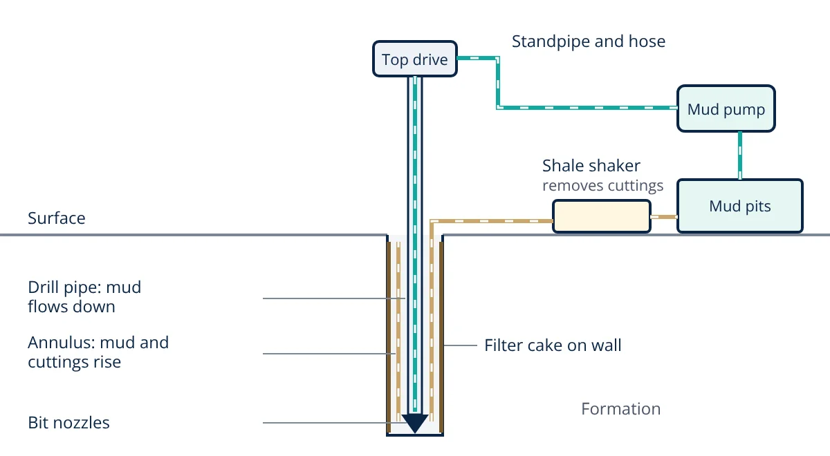
Drilling fluid, or mud, is pumped down the drill string, out through the bit and back up the annulus while a well is drilled. It carries cuttings to surface, controls formation pressure, stabilises the borehole, cools and lubricates the bit and seals permeable rock. The main types are water-based, oil-based, synthetic-based and pneumatic fluids.
Drilling fluid is often called the blood of the drilling operation. It circulates continuously through the well and the surface system, and its properties are measured and adjusted every few hours. A poorly designed drilling fluid can lead to stuck pipe, lost circulation, a collapsed hole or a blowout, so mud engineering is a central part of well design. The equipment that circulates it is described in rotary drilling rig components.
Functions of drilling fluid
According to the API and standard drilling texts, a drilling fluid must:
- Remove cuttings from the bit and carry them to surface. The annular velocity and the viscosity of the mud lift the rock chips; at surface the shale shakers and other solids control equipment separate them.
- Control formation pressure. The hydrostatic pressure of the mud column must exceed the pore pressure of the rock to stop formation fluids entering the well, but stay below the pressure that would fracture the rock. This is the first barrier in well control.
- Maintain wellbore stability. Mud pressure supports the borehole wall, and mud chemistry stops shale from swelling or dissolving salt.
- Seal permeable formations. As liquid filters into porous rock, the solids form a thin, low permeability filter cake on the wall. This limits fluid loss and formation damage, which matters because of the rock’s porosity and permeability.
- Suspend cuttings and weighting material when circulation stops. Gel strength builds when the mud is still, so solids do not settle around the bit.
- Cool and lubricate the bit and drill string.
- Transmit hydraulic power to the bit and downhole tools. Jets in the bit clean the hole bottom, and mud drives mud motors and sends measurement while drilling signals as pressure pulses.
- Support formation evaluation. Cuttings and gas carried by the mud are analysed at surface, and the mud must allow well logging tools to work.
Types of drilling fluid
Water-based mud (WBM)
Water is the continuous phase. WBM is the most widely used and the cheapest system. Variants include:
- Fresh water and spud muds: water with bentonite, for shallow hole sections.
- Dispersed muds: use thinners such as lignosulfonates to control viscosity at high solids content.
- Polymer muds: use polymers such as xanthan gum and polyanionic cellulose for viscosity and fluid loss control with low solids.
- Inhibitive muds: add salts such as potassium chloride, or glycols, to reduce shale swelling.
- Saturated salt muds: used when drilling through salt to avoid dissolving it.
Oil-based mud (OBM)
Oil is the continuous phase, with brine droplets emulsified in it, so it is called an invert emulsion. The water phase is usually calcium chloride brine, and emulsifiers and organophilic clays are added. OBM gives excellent shale stability, lubricity and temperature tolerance, but costs more and its cuttings face strict disposal rules.
Synthetic-based mud (SBM)
SBM replaces diesel or mineral oil with synthetic base fluids such as olefins or esters. It performs like OBM but with lower toxicity, so it was developed to allow use in offshore areas with tight discharge rules.
Pneumatic fluids
Air, mist, foam and aerated mud use gas as all or part of the fluid. They give fast drilling in hard, dry rock and are used for underbalanced drilling of depleted or easily damaged zones, but they cannot control high pressure formations.
Drilling fluid additives
| Additive group | Example materials | Purpose |
|---|---|---|
| Viscosifiers | Bentonite, xanthan gum, organophilic clay | Carry and suspend cuttings |
| Weighting agents | Barite (specific gravity about 4.2), hematite, calcium carbonate | Raise density for pressure control |
| Fluid loss control | Starch, polyanionic cellulose | Build a thin, tight filter cake |
| Thinners and dispersants | Lignosulfonates, lignites | Reduce viscosity and gel strength |
| Shale inhibitors | Potassium chloride, glycols, polyamines | Limit clay swelling |
| Lost circulation materials | Graded calcium carbonate, fibres, flakes | Plug fractures and pores where mud is lost |
| pH and alkalinity | Caustic soda, lime | Control chemistry and corrosion |
Key properties of drilling fluid
Field tests follow API RP 13B-1 for water-based fluids and API RP 13B-2 for oil-based fluids:
- Density (mud weight): measured with a mud balance, in kg/m³, specific gravity or pounds per gallon (ppg).
- Funnel viscosity: seconds for one quart to drain from a Marsh funnel; fresh water takes about 26 s. It is a quick trend check only.
- Plastic viscosity (PV) and yield point (YP): from a rotational viscometer at 600 and 300 rpm, using the Bingham plastic model. PV reflects solids content; YP reflects the attraction between particles and the ability to carry cuttings.
- Gel strength: readings after 10 seconds and 10 minutes at rest.
- API fluid loss: filtrate collected in 30 minutes through filter paper at a differential pressure of 100 psi (690 kPa), plus filter cake thickness. A high pressure, high temperature (HPHT) version is used for deeper wells.
- Solids, sand content, pH, chlorides and, for OBM, oil to water ratio and electrical stability.
The bottom hole hydrostatic pressure of the mud column is:
where h is the true vertical depth (TVD). Rheology from viscometer dial readings θ600 and θ300 is:
with PV in cP and YP in lb/100 ft² (1 lb/100 ft² = 0.4788 Pa).
- Given
- A well is drilled to a true vertical depth of 3000 m with mud of density 1260 kg/m³. The formation pore pressure at that depth is 35.0 MPa. Viscometer readings are θ600 = 52 and θ300 = 32.
- Find
- The bottom hole hydrostatic pressure, the overbalance, and the plastic viscosity and yield point.
- Assumptions
- Static mud column (no circulating friction), uniform density, g = 9.81 m/s², Bingham plastic model.
- Solution
- P_h = 1260 × 9.81 × 3000 = 37 081 800 Pa ≈ 37.1 MPa
Overbalance = 37.1 − 35.0 = 2.1 MPa
PV = 52 − 32 = 20 cP
YP = 32 − 20 = 12 lb/100 ft² = 12 × 0.4788 ≈ 5.7 Pa
Check in field units: 1260 kg/m³ ≈ 10.5 ppg, 3000 m ≈ 9843 ft, 0.052 × 10.5 × 9843 ≈ 5380 psi ≈ 37.1 MPa - Answer
- About 37.1 MPa at the bottom, an overbalance of about 2.1 MPa, with PV = 20 cP and YP = 12 lb/100 ft² (about 5.7 Pa)
- Limitations
- While circulating, annular friction raises the effective pressure (equivalent circulating density); pulling pipe can lower it by swabbing. Fracture pressure must also be checked.
Key formulas for drilling fluid
| Quantity | Formula | Symbols and units |
|---|---|---|
| Hydrostatic pressure (SI) | P_h = ρgh | ρ in kg/m³, g = 9.81 m/s², h = TVD in m, P in Pa |
| Hydrostatic pressure (field) | P_h = 0.052 × MW × TVD | P in psi, MW in ppg, TVD in ft |
| Pressure gradient | G = ρg | Pa/m (1260 kg/m³ gives about 12.4 kPa/m) |
| Plastic viscosity | PV = θ600 − θ300 | cP |
| Yield point | YP = θ300 − PV | lb/100 ft²; × 0.4788 for Pa |
| Overbalance | ΔP = P_h − P_pore | Pa or psi |
Selecting a drilling fluid
Selection balances well conditions, cost and environmental rules. Engineers consider the pore and fracture pressure window, formation type (reactive shale, salt, depleted sands), temperature, hole angle, the need to protect the reservoir, logging requirements, local discharge regulations and the cost of mud and waste handling. Offshore wells, discussed in offshore platform types, often use synthetic-based mud for the deeper sections and water-based mud for the top hole.
Drilling fluid interview and viva questions
- What are the main functions of drilling fluid? It carries cuttings to surface, controls formation pressure, stabilises the borehole, seals permeable formations with a filter cake, suspends solids when static, and cools and lubricates the bit.
- How is bottom hole hydrostatic pressure calculated? P_h = ρgh in SI units, or 0.052 × mud weight in ppg × TVD in ft to give psi.
- How are plastic viscosity and yield point found? From viscometer readings: PV = θ600 − θ300 and YP = θ300 − PV.
- What is an invert emulsion mud? An oil-based or synthetic-based mud in which oil is the continuous phase and brine is dispersed as droplets.
- Why is barite added to drilling mud? It is a dense, inert mineral with a specific gravity of about 4.2 that raises mud density to balance formation pressure.
Frequently asked questions
What happens if mud weight is too low or too high?
If the mud weight is too low, the hydrostatic pressure in the well can fall below the formation pore pressure, so oil, gas or water flows into the wellbore, which is called a kick. If it is too high, the pressure can fracture weak formations and mud is lost into the rock. Mud weight must stay inside the window between pore pressure and fracture pressure.
Why is barite used in drilling mud?
Barite (barium sulphate) is dense, with a specific gravity of about 4.2, chemically inert, soft enough not to wear equipment badly and cheap. Adding it raises the mud density so that the mud column can balance high formation pressures. API Specification 13A sets the quality requirements for drilling grade barite.
When is oil-based mud preferred over water-based mud?
Oil-based or synthetic-based mud is preferred in reactive shales that swell in water, in high temperature wells, in salt sections and in long deviated or horizontal wells where lubricity matters. Its drawbacks are higher cost, stricter rules for disposing of cuttings and more difficult detection of gas kicks.
References
- API RP 13B-1, Field Testing Water-based Drilling Fluids, American Petroleum Institute
- API RP 13B-2, Field Testing Oil-based Drilling Fluids, American Petroleum Institute
- API Specification 13A, Drilling Fluids Materials, American Petroleum Institute
- A. T. Bourgoyne, K. K. Millheim, M. E. Chenevert and F. S. Young, Applied Drilling Engineering, SPE Textbook Series Vol. 2, Society of Petroleum Engineers
- R. Caenn, H. C. H. Darley and G. R. Gray, Composition and Properties of Drilling and Completion Fluids, 7th ed., Gulf Professional Publishing
- ASME Shale Shaker Committee, Drilling Fluids Processing Handbook, Elsevier
Get one engineering email a week
New articles, worked examples and study notes every week. Free, no spam, unsubscribe any time.