Landfill Design: Liners, Leachate and Gas
Landfill design is the engineering of a sanitary landfill that isolates waste from soil, water and air. It combines careful siting, a composite liner of geomembrane over compacted clay, a leachate collection and treatment system, landfill gas extraction, daily and final cover, and long term monitoring of groundwater and gas after closure.
Landfill design turns waste disposal from an open dump into a controlled engineering system. Even with strong recycling and composting, every city produces residual waste that must go somewhere, and the landfill is the last step in the solid waste management hierarchy. A poorly designed site pollutes groundwater with leachate, releases methane and can suffer slope failures. A well designed site contains these risks for decades.
Main elements of landfill design
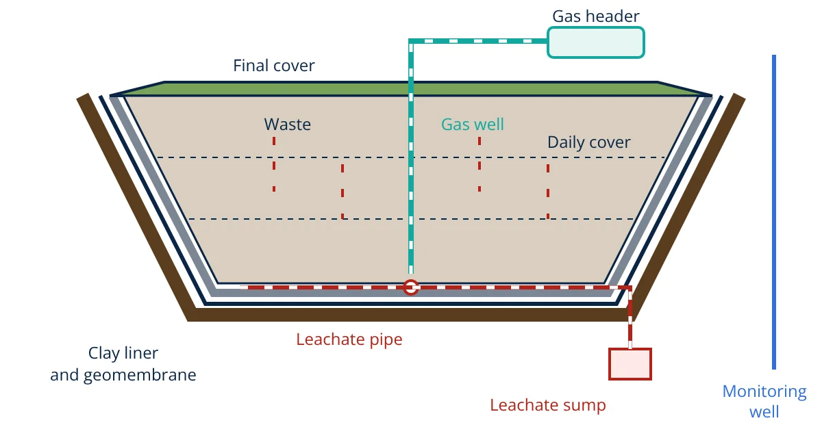
A modern municipal landfill is built as a series of lined cells filled in lifts. Working from the bottom up, the main elements are:
- Prepared subgrade: a stable, graded base above the seasonal high groundwater level.
- Liner system: a composite barrier of compacted clay and a geomembrane, often with a geotextile cushion.
- Leachate collection system: a drainage layer and perforated pipes on the liner that lead to sumps.
- Waste body: waste spread in thin layers, compacted and covered daily.
- Gas collection system: vertical wells and horizontal collectors connected to a header and blower.
- Final cover (cap): a low permeability barrier with drainage and a vegetated soil layer.
- Monitoring network: groundwater wells around the site and gas probes at the boundary.
Site selection
Good landfill design starts with the site. US EPA rules in 40 CFR Part 258 restrict new municipal landfills near airports (because birds attracted to waste are a hazard to aircraft), in 100 year floodplains, in wetlands, near active faults, in seismic impact zones and in geologically unstable areas. The Indian Solid Waste Management Rules, 2016 and the CPHEEO manual add criteria on distance from habitation, water bodies and highways. An environmental impact assessment normally compares candidate sites on geology, hydrogeology, access and public acceptance. A deep water table and low permeability natural soil are strong advantages, and the subgrade must have adequate bearing capacity for the weight of waste and cover.
Liner systems in landfill design
The liner is the heart of containment. 40 CFR 258.40 sets a composite liner as the design standard for new US municipal landfills: an upper flexible membrane liner of at least 30 mil (0.75 mm), or at least 60 mil (1.5 mm) if it is high density polyethylene (HDPE), in direct contact with at least 0.6 m (2 ft) of compacted soil with a hydraulic conductivity no greater than 1 × 10⁻⁷ cm/s. The Indian SWM Rules, 2016 specify a similar composite barrier: a 1.5 mm HDPE geomembrane, or equivalent, over 90 cm of clay or amended soil with permeability not greater than 1 × 10⁻⁷ cm/s.
Direct contact matters. Qian, Koerner and Gray explain that leakage through a geomembrane occurs at small holes and seam defects; if the clay is pressed tightly against the membrane, liquid cannot spread sideways along the interface and the flow through each hole stays small. Hazardous waste landfills often use a double liner with a leak detection layer between the two barriers.
Geosynthetics used around the liner include:
- Geotextiles: cushion the geomembrane from stones and act as filters.
- Geonets and geocomposites: thin drainage layers in the leachate system and the cap.
- Geosynthetic clay liners (GCL): factory made bentonite layers sometimes used instead of part of the compacted clay where regulators allow.
Leachate collection and treatment
Leachate forms when rainwater percolates through the waste and picks up dissolved and suspended matter from decomposition. Its volume can be estimated with a water balance over the landfill surface:
where L is leachate, P precipitation, R surface runoff, ET evapotranspiration and ΔS the change in moisture stored in the cover and waste (Tchobanoglous). Covering filled areas quickly and grading the cap to shed runoff cuts leachate production.
The collection system is a granular or geocomposite drainage layer on the liner with perforated pipes laid to fall towards sumps. 40 CFR 258.40 requires it to keep the depth of leachate on the liner below 30 cm, because a lower head on the liner means lower leakage. Pumps lift the leachate to storage and treatment. Treatment trains combine biological processes similar to the activated sludge process with membrane steps such as reverse osmosis to remove ammonia, organics and salts.
Landfill gas control
Organic waste in a landfill decomposes anaerobically. The US EPA Landfill Methane Outreach Program describes landfill gas as roughly half methane and half carbon dioxide, with small amounts of other gases. Methane is explosive and a strong greenhouse gas, so landfill design must control it.
- Active systems: vertical wells and horizontal trenches connected to a header under vacuum from a blower. The gas is flared or used in engines, boilers or upgraded to biomethane.
- Passive systems: vents and gravel trenches that let gas escape to the atmosphere or block lateral migration.
40 CFR 258.23 limits methane to 25% of its lower explosive limit inside facility structures and to the lower explosive limit at the property boundary, with routine monitoring.
Daily cover, final cover and closure
At the end of each operating day, US rules require at least 15 cm (6 in) of earthen material, or an approved alternative, over the exposed waste to control odour, litter, fires, birds and vectors. When the landfill is full, a final cover is placed. 40 CFR 258.60 requires an infiltration layer of at least 45 cm (18 in) of earthen material with permeability no greater than that of the bottom liner or 1 × 10⁻⁵ cm/s, whichever is less, topped by an erosion layer of at least 15 cm (6 in) of soil able to support plants. Many caps also include a geomembrane and a drainage layer. Post closure care, including monitoring and maintenance, normally lasts 30 years.
Worked example: leakage through a clay liner
Darcy’s law shows why a geomembrane is added on top of the clay. Flow through a saturated clay liner of area A is:
where k is hydraulic conductivity, h the leachate head on the liner and d the liner thickness.
- Given
- A clay only liner 0.6 m thick with k = 1 × 10⁻⁷ cm/s, leachate head 0.3 m (the maximum allowed by 40 CFR 258.40), liner area 1 hectare (10 000 m²).
- Find
- Leakage rate through the clay.
- Assumptions
- Steady, saturated, one dimensional vertical flow; free drainage below the liner; no geomembrane.
- Solution
- k = 1 × 10⁻⁷ cm/s = 1 × 10⁻⁹ m/s
i = (0.3 + 0.6) ÷ 0.6 = 1.5
Q = 1 × 10⁻⁹ × 1.5 × 10 000 = 1.5 × 10⁻⁵ m³/s
Daily = 1.5 × 10⁻⁵ × 86 400 = 1.30 m³/day
Yearly = 1.296 × 365 = 473 m³/year - Answer
- About 1.3 m³ of leachate per day, or roughly 470 m³ per year, per hectare of clay only liner
- Limitations
- Real clay may be unsaturated or cracked, and the head varies with rainfall. A geomembrane in direct contact with the clay reduces leakage to flow through occasional holes, which is far smaller.
Key formulas for landfill design
| Quantity | Formula | Symbols and units |
|---|---|---|
| Leachate water balance | L = P − R − ET − ΔS | All terms as depth of water (mm) over the landfill area per period |
| Hydraulic gradient across liner | i = (h + d) ÷ d | h = leachate head in m, d = liner thickness in m |
| Darcy leakage | Q = k × i × A | k in m/s, A in m², Q in m³/s |
| Unit conversion | 1 cm/s = 0.01 m/s | 1 × 10⁻⁷ cm/s = 1 × 10⁻⁹ m/s |
Monitoring and operation
A landfill design is only as good as its operation. Groundwater monitoring wells upgradient and downgradient of the cells detect any leak early, with sampling on a regular schedule set by the regulator. Gas probes around the boundary check for migration. Operators record leachate volumes, inspect slopes and cover for cracks and erosion, and keep the working face small. Diverting organics to composting and biogas, as described in circular economy principles, reduces both leachate strength and methane generation.
Landfill design interview and viva questions
- What are the main components of landfill design? Site selection, a composite liner, leachate collection and treatment, landfill gas control, daily cover, final cover and long term groundwater and gas monitoring.
- What composite liner does 40 CFR 258.40 specify? A geomembrane of at least 30 mil, or 60 mil for HDPE, in direct contact with at least 0.6 m of compacted soil with hydraulic conductivity no greater than 1 × 10⁻⁷ cm/s.
- Why is the leachate head on the liner limited to 30 cm? Leakage through any defect increases with the head of liquid on the liner, so keeping the head low limits flow into the ground.
- What is landfill gas made of and why is it controlled? It is roughly half methane and half carbon dioxide; methane can explode when it migrates into buildings and is a powerful greenhouse gas.
- What does the final cover do? It limits rainfall infiltration into the waste, controls gas emission, prevents erosion and supports vegetation after closure.
Frequently asked questions
What is the difference between a dump and a sanitary landfill?
An open dump is uncontrolled: waste is tipped on bare ground with no liner, cover or monitoring, so leachate and gas escape freely. A sanitary landfill is engineered, with a liner, leachate collection, daily cover, gas control, a final cap and groundwater monitoring.
Why is a composite liner better than a clay liner alone?
The geomembrane has extremely low permeability but can have small holes, while the clay below has low permeability and limits flow through any hole. Together the two layers leak far less than either layer alone, which is why US and Indian rules require a composite barrier.
How long must a closed landfill be monitored?
Under US EPA rules in 40 CFR Part 258, post closure care normally lasts 30 years, covering cover maintenance, leachate collection, groundwater monitoring and gas monitoring. The regulator can shorten or extend this period based on site performance.
References
- US EPA, 40 CFR Part 258, Criteria for Municipal Solid Waste Landfills
- Solid Waste Management Rules, 2016, Schedule I, Ministry of Environment, Forest and Climate Change, India
- CPHEEO, Manual on Municipal Solid Waste Management, 2016, Ministry of Urban Development, India
- G. Tchobanoglous, H. Theisen and S. Vigil, Integrated Solid Waste Management, McGraw-Hill
- X. Qian, R. M. Koerner and D. H. Gray, Geotechnical Aspects of Landfill Design and Construction, Prentice Hall, 2002
- US EPA, Landfill Methane Outreach Program (LMOP), Basic Information about Landfill Gas
Get one engineering email a week
New articles, worked examples and study notes every week. Free, no spam, unsubscribe any time.