Shell and Tube Heat Exchanger Design Basics
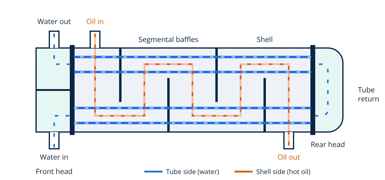
A shell and tube heat exchanger passes one fluid through a bundle of tubes and the other through the surrounding shell, guided by baffles. Design means choosing the TEMA type, fluid allocation, tube size, layout and baffle spacing, then finding the area from Q = U A F ΔTlm and checking pressure drop.
The shell and tube heat exchanger is the workhorse of refineries, chemical plants and power stations. It handles high pressures and temperatures, almost any fluid and duties from a few kilowatts to many megawatts. This guide covers the design basics: how the exchanger is built, how the main geometric choices are made, and how the heat transfer area is calculated. For a comparison with plate, double pipe and air cooled units, see heat exchanger types.
Shell and tube heat exchanger construction
The main parts are:
- Tube bundle: many small tubes that carry the tube side fluid and provide the heat transfer area.
- Tubesheets: thick plates drilled to hold the tube ends, which are rolled or welded in place.
- Shell: the cylindrical vessel around the bundle, with inlet and outlet nozzles for the shell side fluid. It is a pressure vessel and is designed to a pressure vessel code.
- Front head (channel) and rear head: distribute and return the tube side fluid. A pass partition plate in the channel divides the tubes into two or more passes.
- Baffles: plates across the bundle that support the tubes and force the shell side fluid to flow across them, which raises the shell side coefficient.
- Tie rods and spacers: hold the baffles in position.
TEMA types and mechanical arrangement
The TEMA standards name an exchanger with three letters: front head, shell type and rear head. Common examples are:
| TEMA type | Description | Typical use |
|---|---|---|
| BEM | Bonnet, one pass shell, fixed tubesheet | Clean shell side fluid, small temperature difference between shell and tubes |
| AES | Removable channel, one pass shell, split ring floating head | Fouling shell side fluid, large thermal expansion, bundle removal needed |
| AEU | Removable channel, one pass shell, U-tube bundle | High pressure, large expansion, clean tube side fluid |
| AET | Pull through floating head | Easy bundle removal, at the cost of a larger shell clearance |
A fixed tubesheet design is the cheapest but the shell side cannot be cleaned mechanically, and differential expansion between shell and tubes may require an expansion bellows. U-tube and floating head designs let the bundle expand freely and can be withdrawn for cleaning. TEMA also defines three mechanical classes: R for severe petroleum service, C for general commercial service and B for chemical process service.
Key design choices
Fluid allocation
Sinnott and Kern give the usual rules. Put the fluid that is corrosive, fouling, at higher pressure or at higher temperature in the tubes, since alloy tubes are cheaper than an alloy shell and tubes are easier to clean. Put the more viscous fluid, or the stream with the lower flow rate, on the shell side, where cross flow around the baffles gives a higher coefficient. A condensing vapour normally goes on the shell side.
Tube size, length and layout
Tube outside diameters from 16 to 50 mm are used, and 19.05 mm (3/4 inch) and 25.4 mm (1 inch) are the most common. Preferred lengths include 1.83, 2.44, 3.66, 4.88 and 6.10 m. Longer tubes give a smaller, cheaper shell for the same area.
Tubes are laid out on a triangular (30°) or square (90°) pitch. The usual pitch is 1.25 times the tube outside diameter. Triangular pitch packs more tubes in a shell and gives higher coefficients; square pitch leaves straight lanes so the outside of the tubes can be cleaned mechanically, which suits fouling shell side fluids.
Baffles
Single segmental baffles are the most common. The baffle cut is the height of the removed segment as a percentage of shell diameter; 20 to 25% is usual. Baffle spacing is normally 0.2 to 1.0 times the shell inside diameter. Closer spacing raises the shell side coefficient but also the pressure drop, so the designer balances the two.
Velocities and passes
Typical design velocities for liquids are 1 to 2 m/s inside tubes and 0.3 to 1 m/s on the shell side. Higher velocity improves heat transfer and reduces fouling but raises pressure drop and erosion risk. If tube side velocity is too low with one pass, the tubes are split into 2, 4, 6 or more passes.
Shell and tube heat exchanger thermal design method
The heat duty comes from an energy balance on either stream:
The counterflow log mean temperature difference is:
With one shell pass and two or more tube passes, the flow is partly parallel, so the mean difference is F ΔTlm. F depends on two ratios:
The required area is then:
A practical design follows these steps:
- Define duty, flows and temperatures from the heat and material balance.
- Choose TEMA type and fluid allocation.
- Assume a trial U from tables in Sinnott or Perry’s, for example 350 to 900 W/m²K for light oil cooled by water.
- Calculate ΔTlm and F, then the trial area.
- Choose tube size, length and passes, and find the number of tubes and shell diameter.
- Calculate tube side and shell side film coefficients (Kern method or the more accurate Bell Delaware method), add fouling resistances and recalculate U.
- Check pressure drops on both sides and iterate until the area and pressure drops are acceptable.
- Given
- Hot oil, 5 kg/s, cp = 2.3 kJ/kgK, cooled from 150 °C to 90 °C on the shell side. Cooling water on the tube side heats from 25 °C to 45 °C, cp = 4.18 kJ/kgK. One shell pass, two tube passes. Trial U = 350 W/m²K. Tubes 19.05 mm OD, 4.88 m long.
- Find
- Heat duty, water flow, corrected mean temperature difference, area and approximate number of tubes.
- Assumptions
- Steady state, no heat loss to surroundings, constant specific heats, U uniform and based on tube outside area.
- Solution
- Q = 5 × 2.3 × (150 − 90) = 690 kW
Water flow = 690 ÷ (4.18 × 20) = 8.25 kg/s
ΔT1 = 150 − 45 = 105 K, ΔT2 = 90 − 25 = 65 K
ΔTlm = (105 − 65) ÷ ln(105 ÷ 65) = 83.4 K
R = 60 ÷ 20 = 3.0, P = 20 ÷ 125 = 0.16, F = 0.970
A = 690000 ÷ (350 × 0.970 × 83.4) = 24.4 m²
Area per tube = π × 0.01905 × 4.88 = 0.292 m²
Number of tubes = 24.4 ÷ 0.292 = 83.4, so 84 tubes (42 per pass) - Answer
- Q = 690 kW, F ΔTlm = 80.9 K, A ≈ 24.4 m², about 84 tubes of 19.05 mm × 4.88 m
- Limitations
- U is only a trial value. The film coefficients, fouling resistances and pressure drops must be calculated for the chosen geometry and the design repeated until the assumed and calculated U agree.
Key formulas for shell and tube heat exchanger design
| Quantity | Formula | Symbols and units |
|---|---|---|
| Heat duty | Q = ṁ cp ΔT | Q in kW, ṁ in kg/s, cp in kJ/kgK, ΔT in K |
| Log mean temperature difference | ΔTlm = (ΔT1 − ΔT2) ÷ ln(ΔT1 ÷ ΔT2) | ΔT1 = T1 − t2, ΔT2 = T2 − t1, in K |
| Temperature ratios | R = (T1 − T2) ÷ (t2 − t1), P = (t2 − t1) ÷ (T1 − t1) | T = shell side, t = tube side temperatures |
| Design equation | A = Q ÷ (U F ΔTlm) | A in m², U in W/m²K, F dimensionless |
| Area per tube | a = π do L | do = tube outside diameter, L = tube length, in m |
Fouling, pressure drop and practical checks
Fouling resistances from TEMA tables or plant experience are added in series with the film resistances, which lowers U and increases area. Over-generous fouling allowances are a common cause of oversized exchangers. Pressure drop on each side must stay within the allowable value, often set by the pump or compressor available. A centrifugal pump supplying cooling water, for example, has a limited head. Designers also check for a temperature cross, tube vibration from high shell side velocity, and enough clearance to pull the bundle. Heat recovery networks built from many exchangers are optimised with pinch analysis.
Shell and tube heat exchanger interview and viva questions
- What is the purpose of baffles in a shell and tube heat exchanger? Baffles support the tubes against sagging and vibration and direct the shell side fluid across the tube bundle, which raises the shell side heat transfer coefficient.
- Why is triangular pitch preferred over square pitch? It fits more tubes in a given shell and gives higher coefficients. Square pitch is chosen when the shell side must be cleaned mechanically.
- What is the F correction factor? It is the ratio of the true mean temperature difference in a multipass exchanger to the counterflow LMTD. It is found from R and P and should generally be above about 0.75.
- When would you choose a U-tube exchanger? When there is a large temperature difference between shell and tubes, the pressure is high and the tube side fluid is clean, since U-tubes expand freely but are hard to clean inside the bends.
- Which fluid would you put in the tubes if one stream is corrosive? The corrosive stream goes in the tubes, so only the tubes, tubesheets and channel need costly alloy instead of the whole shell.
Frequently asked questions
Which fluid goes on the tube side of a shell and tube heat exchanger?
Usually the more corrosive, the more fouling, the higher pressure or the higher temperature fluid goes in the tubes, because tubes are cheaper to make in alloy, easier to clean and stronger under pressure than the shell. Very viscous fluids or low flow streams often go on the shell side, where baffles give better heat transfer.
What does a TEMA designation such as AES mean?
TEMA uses three letters for the front head, the shell and the rear head. AES means a removable channel and cover (A), a one pass shell (E) and a split ring floating head (S). BEM is a bonnet, one pass shell and fixed tubesheet, and AEU has a U-tube bundle.
Why must the F correction factor stay above about 0.75?
In a multipass exchanger the flow is not pure counterflow, so the true mean temperature difference is F times the counterflow LMTD. Below about 0.75 the value of F changes steeply with small changes in temperatures, so the design becomes unreliable and may even involve a temperature cross. More shell passes or shells in series are then used.
References
- Standards of the Tubular Exchanger Manufacturers Association (TEMA), 10th ed., 2019
- D. Q. Kern, Process Heat Transfer, McGraw-Hill
- R. K. Sinnott, Coulson and Richardson's Chemical Engineering, Vol. 6: Chemical Engineering Design, 4th ed., Elsevier Butterworth-Heinemann
- D. W. Green and R. H. Perry (eds.), Perry's Chemical Engineers' Handbook, 8th ed., McGraw-Hill, Section 11: Heat Transfer Equipment
- F. P. Incropera, D. P. DeWitt, T. L. Bergman and A. S. Lavine, Fundamentals of Heat and Mass Transfer, 7th ed., Wiley
Get one engineering email a week
New articles, worked examples and study notes every week. Free, no spam, unsubscribe any time.